Volvo 670
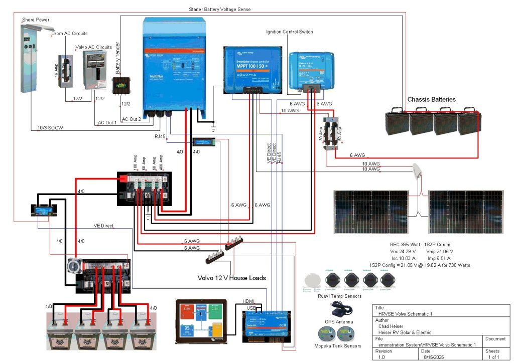
System Schematic
Basic Parts List
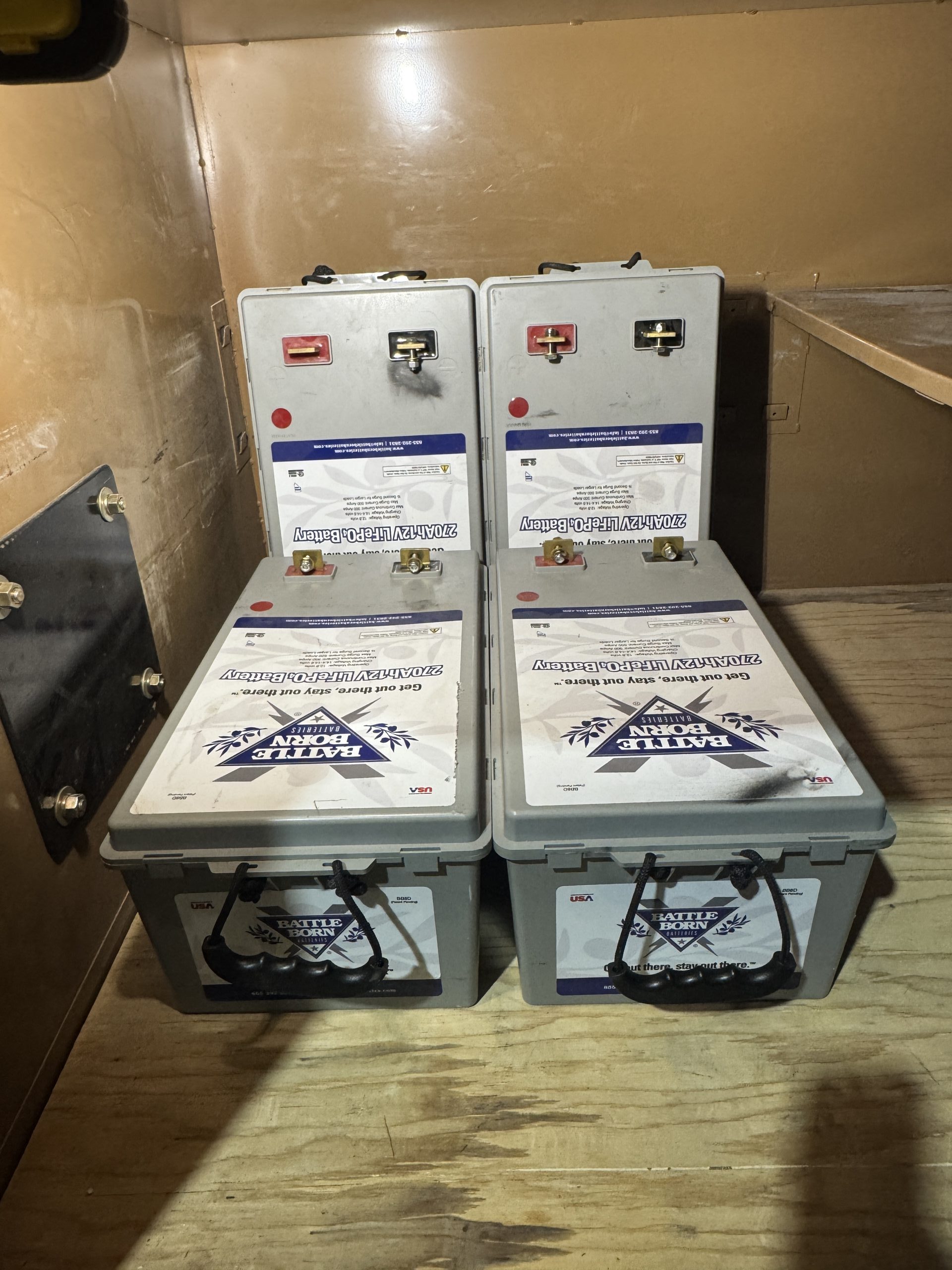
- 4 -Battle Born 8D 270 amp lithium batteries
- Victron Multiplus 12/3000/120 inverter charger
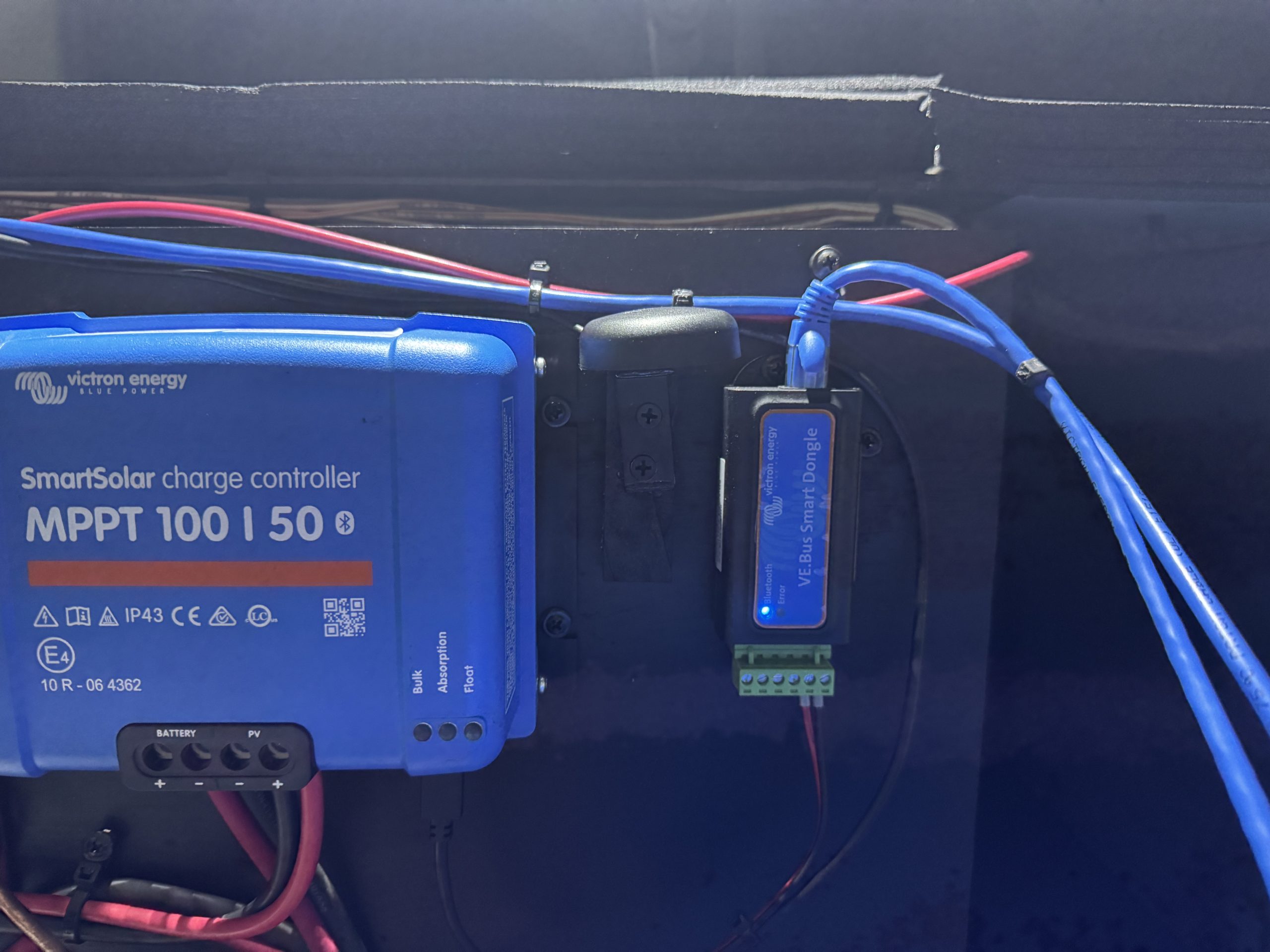
- Victron VE.Bus Smart Dongle – allows Bluetooth connectivity to Multiplus
- Victron MPPT 100/50 Smart Solar charge controllers with built in Bluetooth
- Victron 500 amp SmartShunt
- Victron Lynx Distributor
- Various Victron Mega Fuses for Lynx Distributor
- 7 Feet 2 AWG Welding Cable - Red
- 7 Feet 2 AWG Welding Cable - Black
- 20 Feet 4/0 Welding Cable - Red
- 2 Feet 4/0 Welding Cable - Black
- 3 Feet 6 AWG Bare Copper Cable
- 15 Feet 12/2 Romex Cable
- 20 Feet 10 AWG PV Wire
- 2 - REC 365 Watt Solar Panels
- Blue Sea 3000 Battery Switch HD On/Off
- 2 - Midnite Solar Baby Boxes
- 30A & 60 A 150 V MNEPV DC DIN Mounted Breakers for Midnite Solar Baby Box
- Red Dual Wall Shrink Tubing
- Black Dual Wall Shrink Tubing
- Various 4/0 Tinned Copper Lugs
- Various 2 AWG Tinned Copper Lugs
- Various 6 AWG Tinned Copper Lugs
- MC4 Male/Female Solar Panel Cable Connectors& MC4 Y Connector
- RuuviTag Temperature Sensors and Mopeka Pro Check Water Sensors
- Miscellaneous parts, sealants, breakers, and connectors
Installation Notes
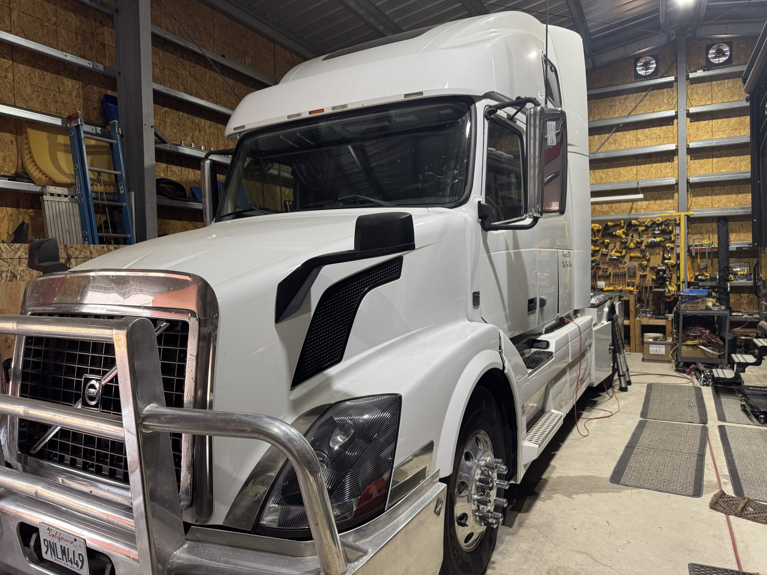
This installation was completed in August of 2025. This is my personal tow vehicle to tow my DRV Full House MX450 toy hauler. I recently upgraded the battery system in my DRV and had four Battle Born 8D batteries available as a result. (Click here to see how I upgraded the DRV battery bank and reconfigured the Victron system installed there as a result.) I decided to install these batteries in my Volvo as a separate house bank and upgrade the existing Xantrex inverter charger to a complete Victron system.
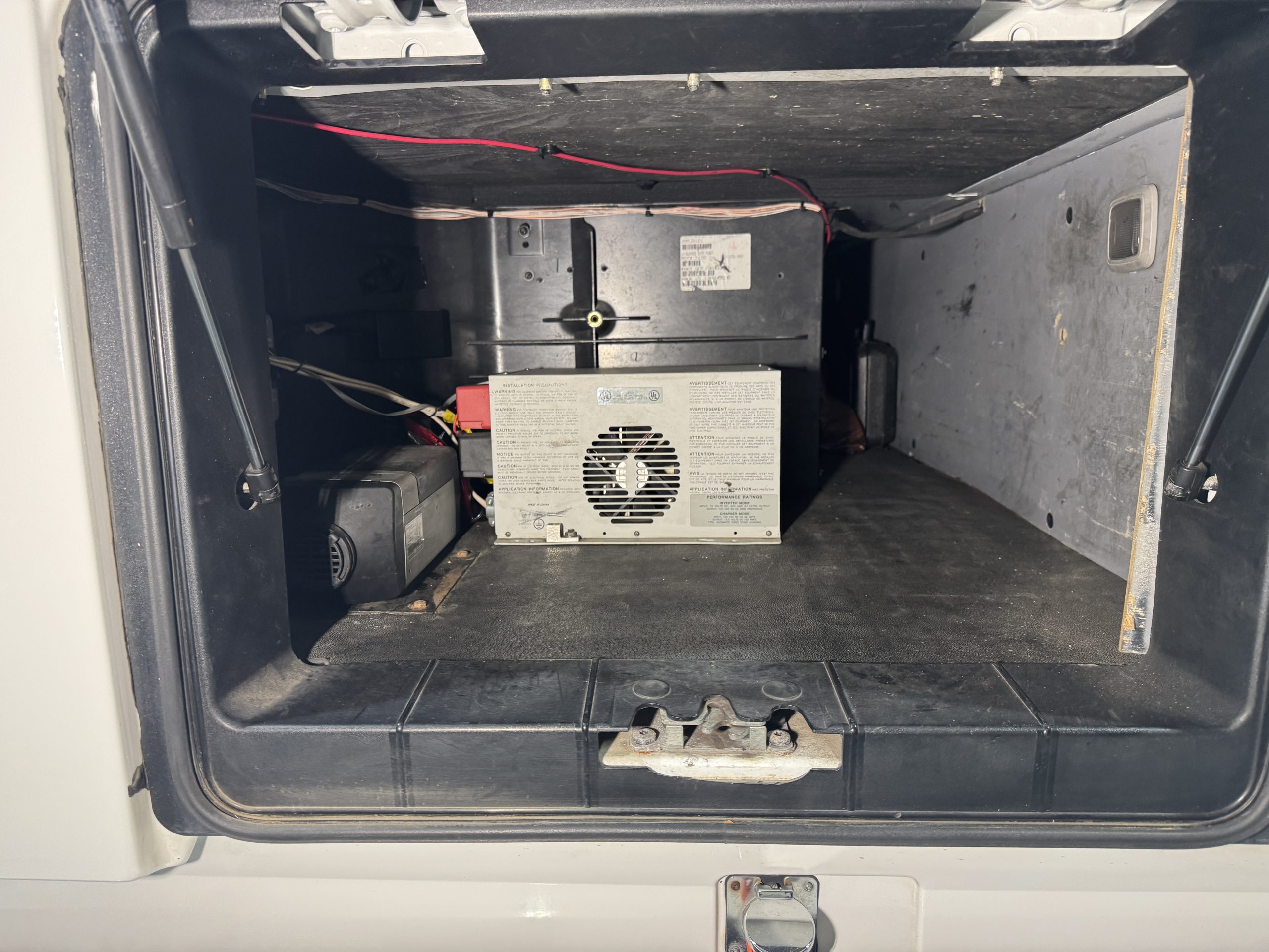
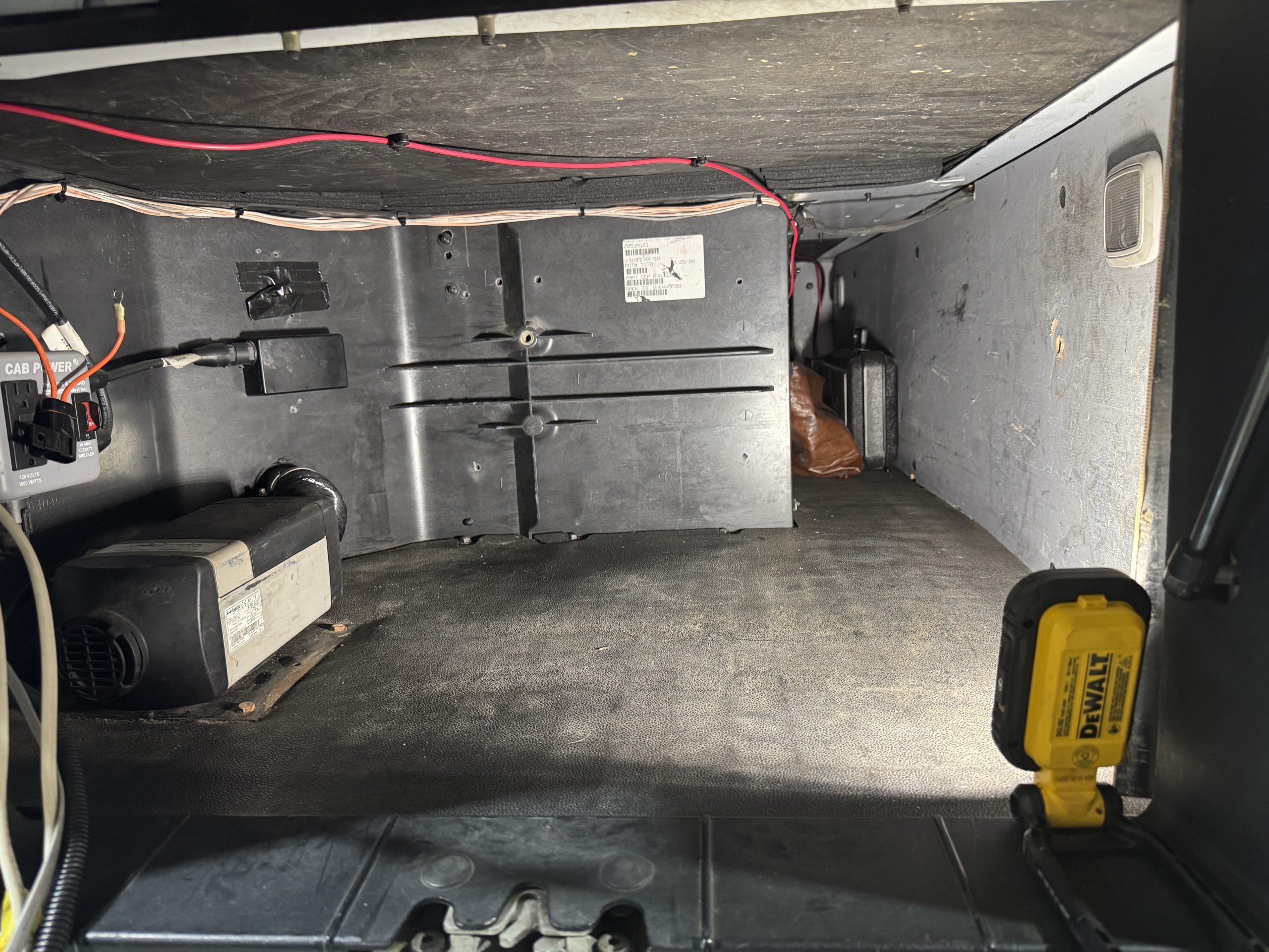
The installation took approximately three days to complete (although I was working on it intermittently as I had time between other projects). First I had to remove the existing Xantrex Freedom inverter charger and its related wiring. I also cleaned up some existing funky chassis battery wiring connections. I then began the installation process in earnest. Initially, I planned to just use one or two of the Battle Born 8D batteries and try to install the entire system in the driver’s side Jockey box of the sleeper. Once I started trying to layout the system components to figure out the best equipment layout, I quickly discovered I was not going to be able to make the batteries and the Victron equipment all fit in the Jockey box. This led me to just put the Victron equipment in the Jockey box and move the batteries to the drom storage box on the custom hauler bed of the truck. The drom box was a much larger space and this allowed me to keep all four batteries in the system.
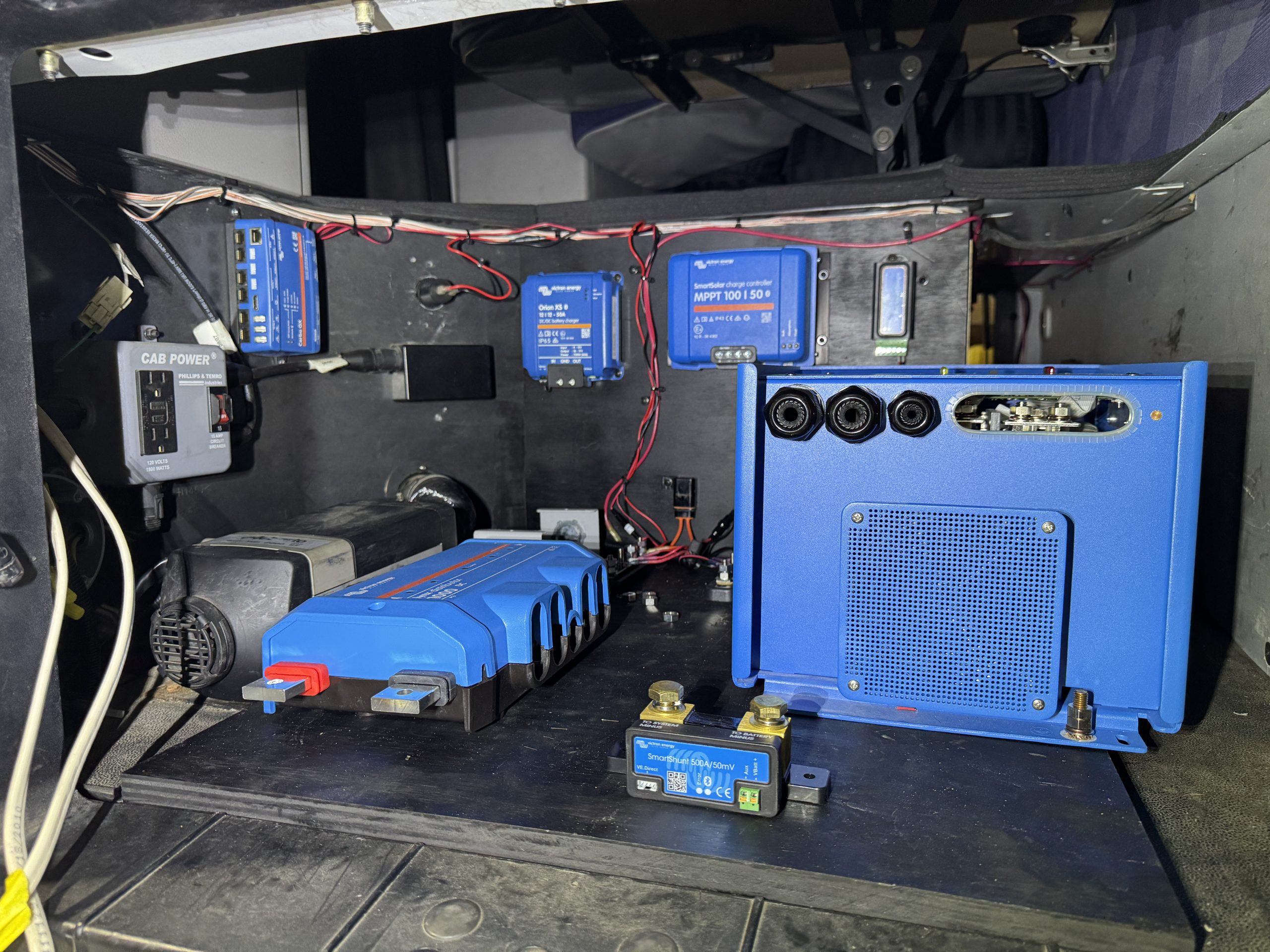
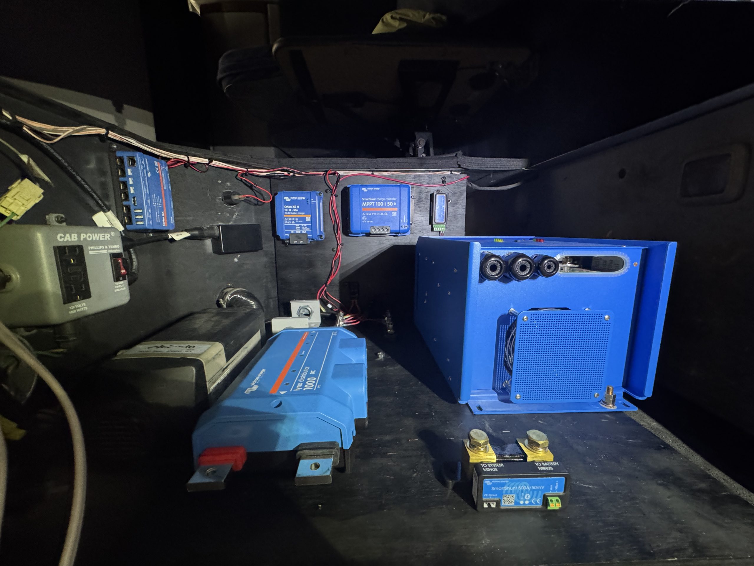
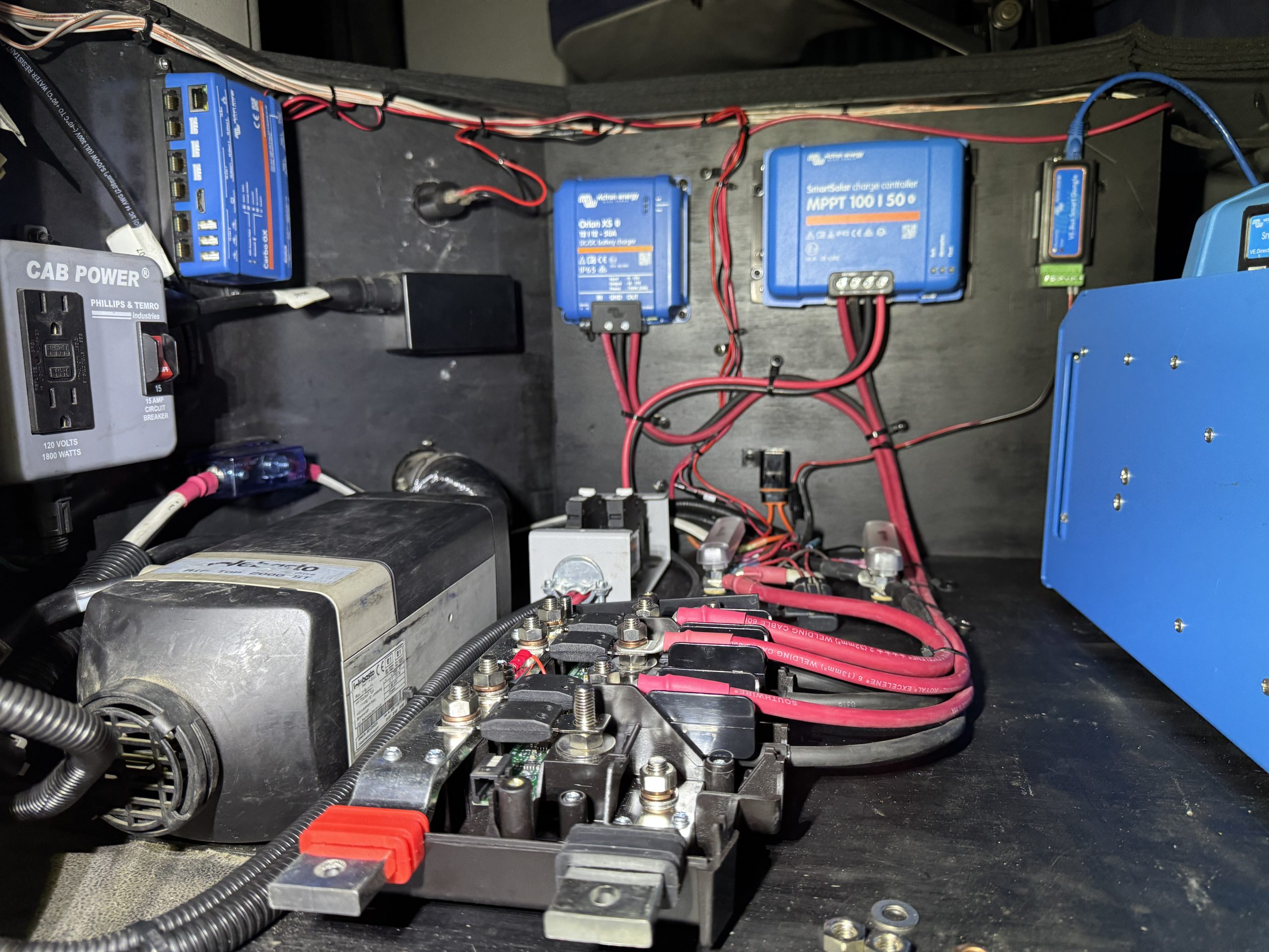
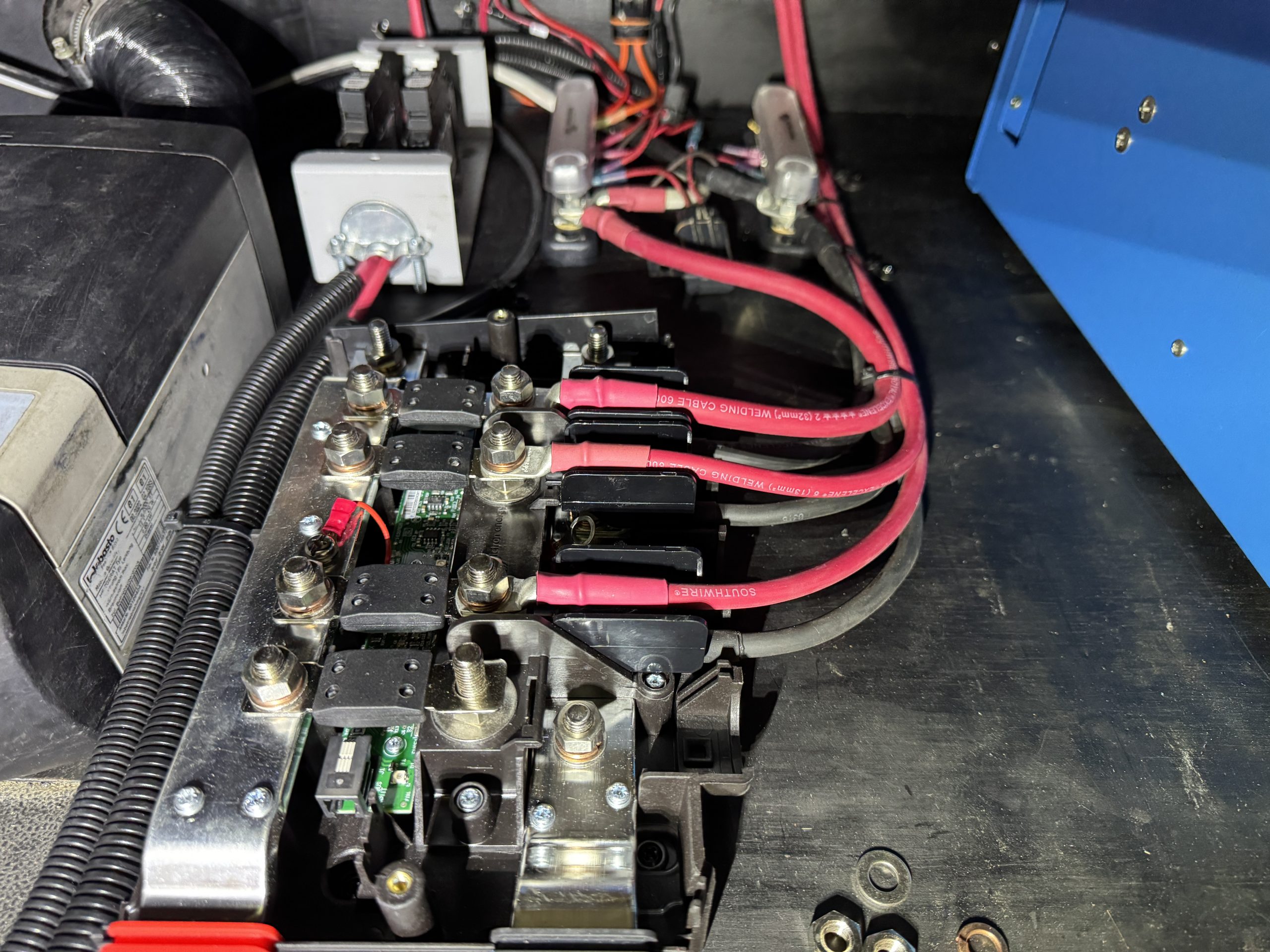
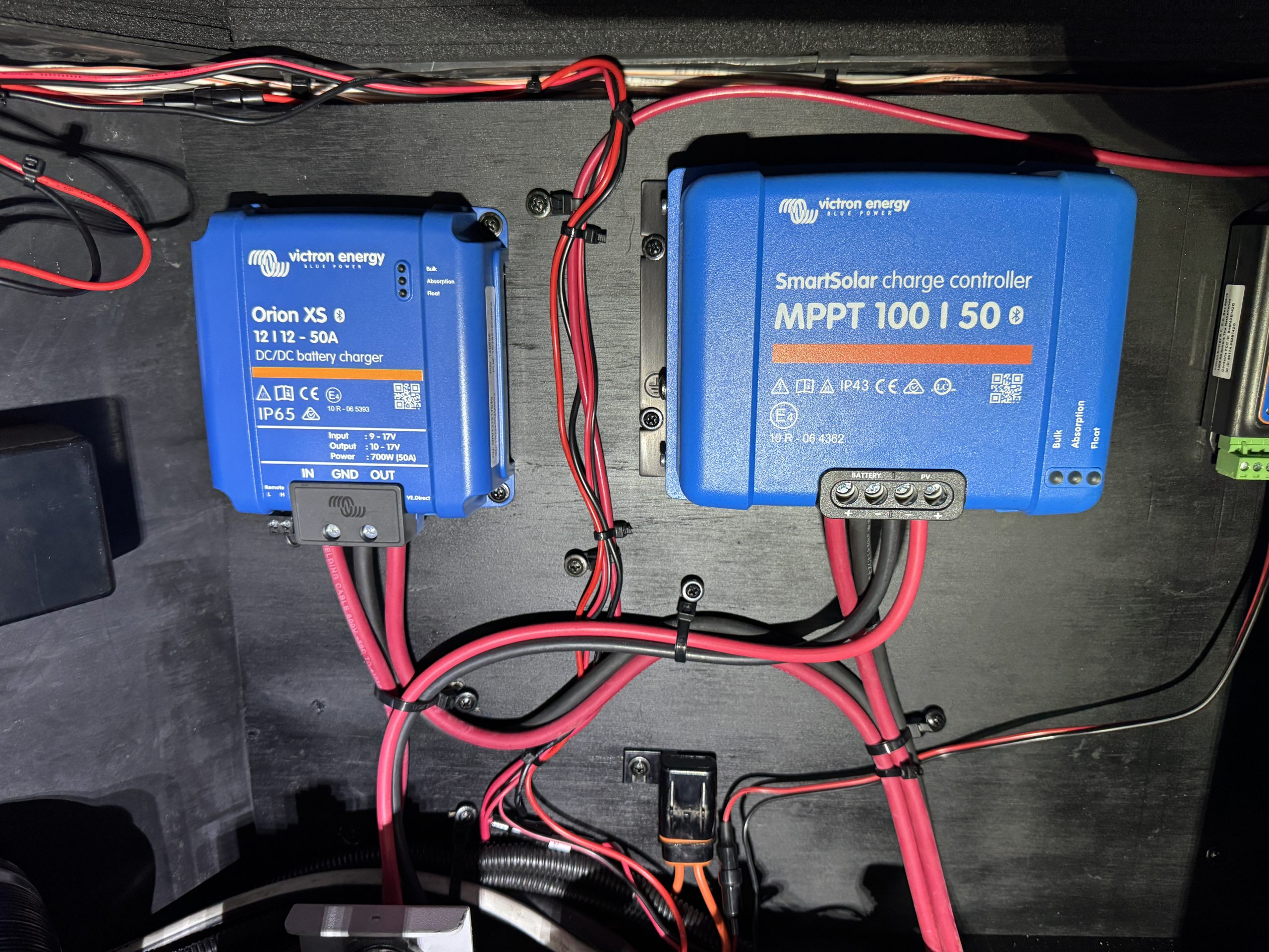
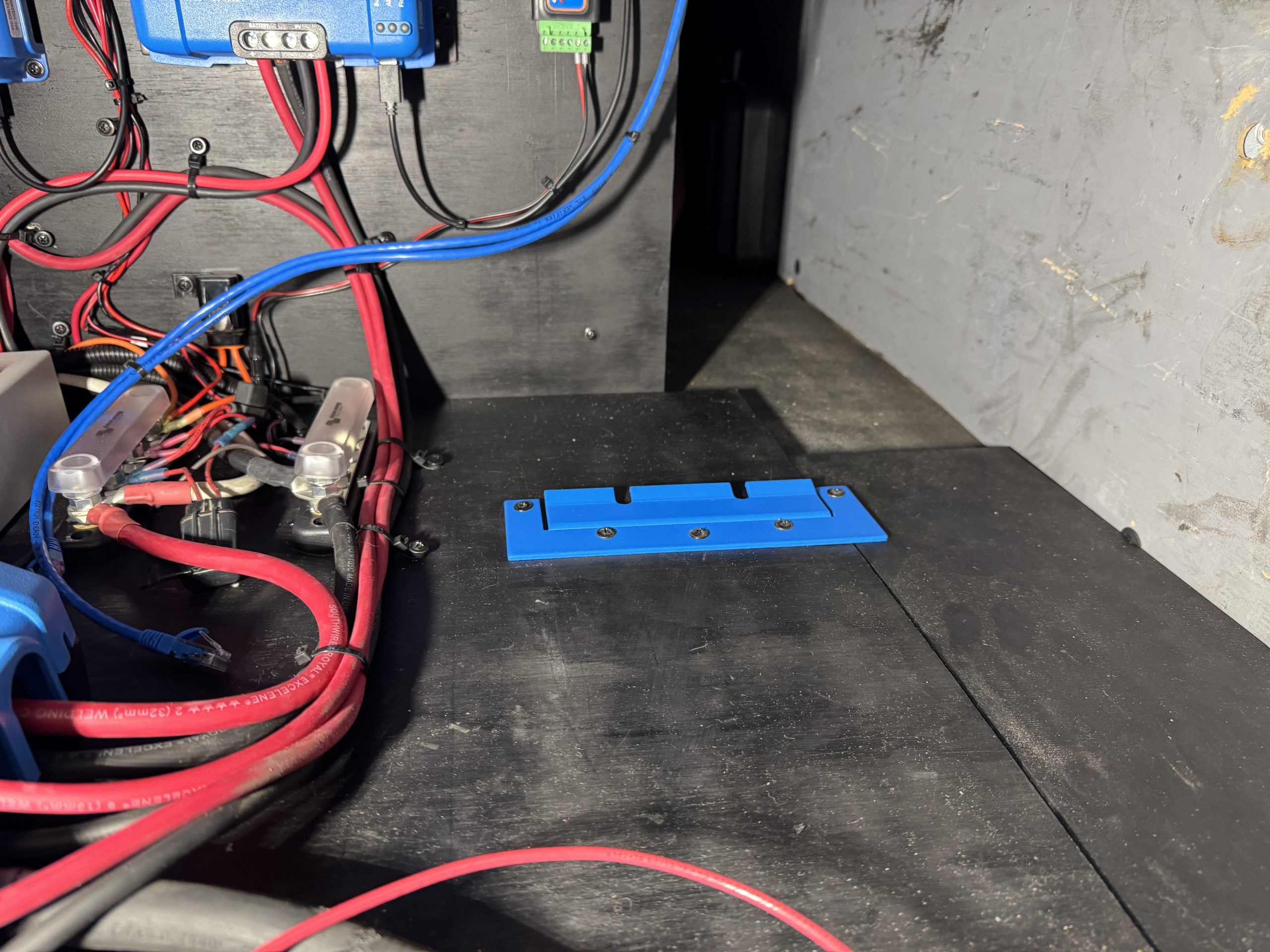
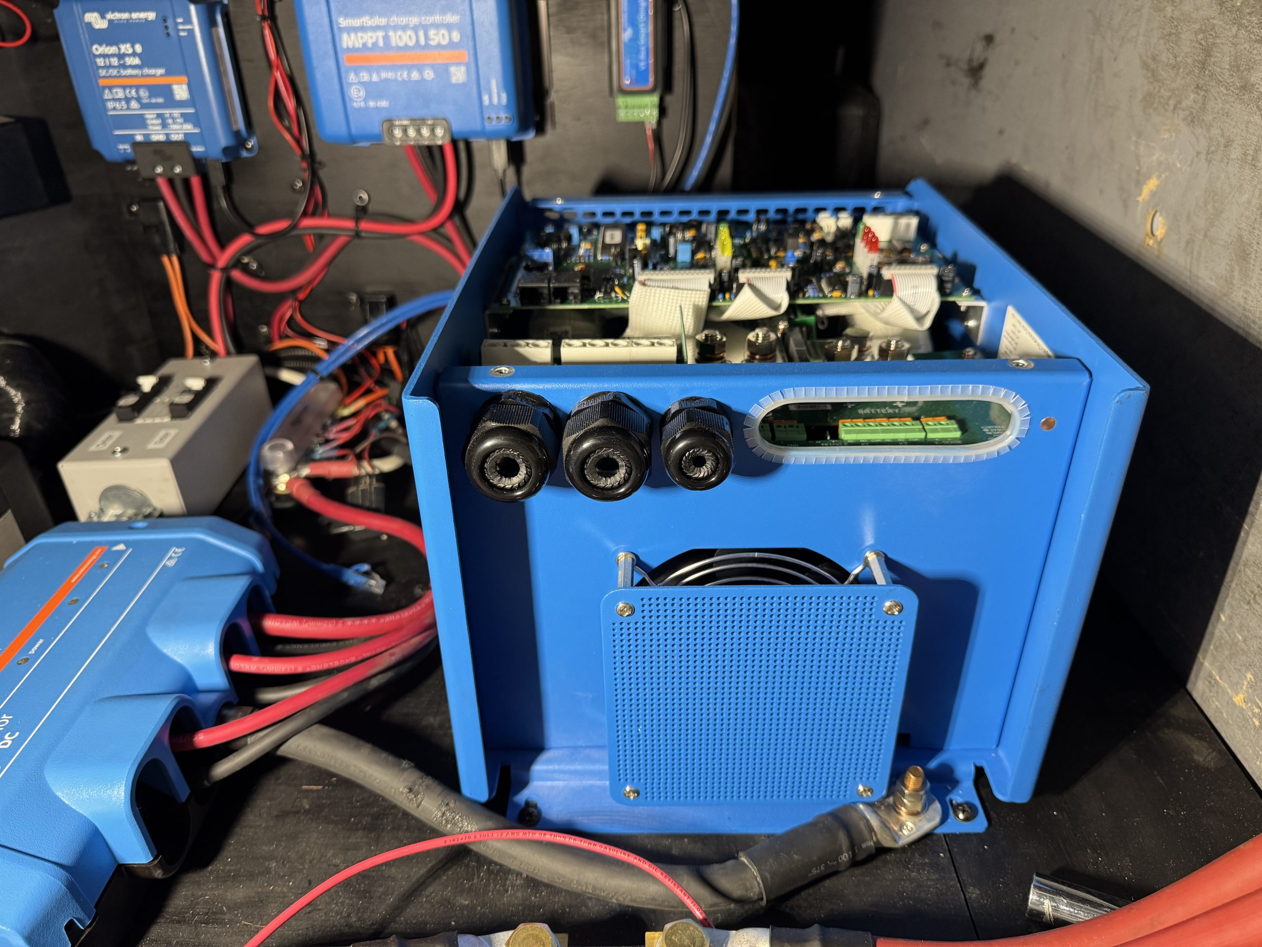
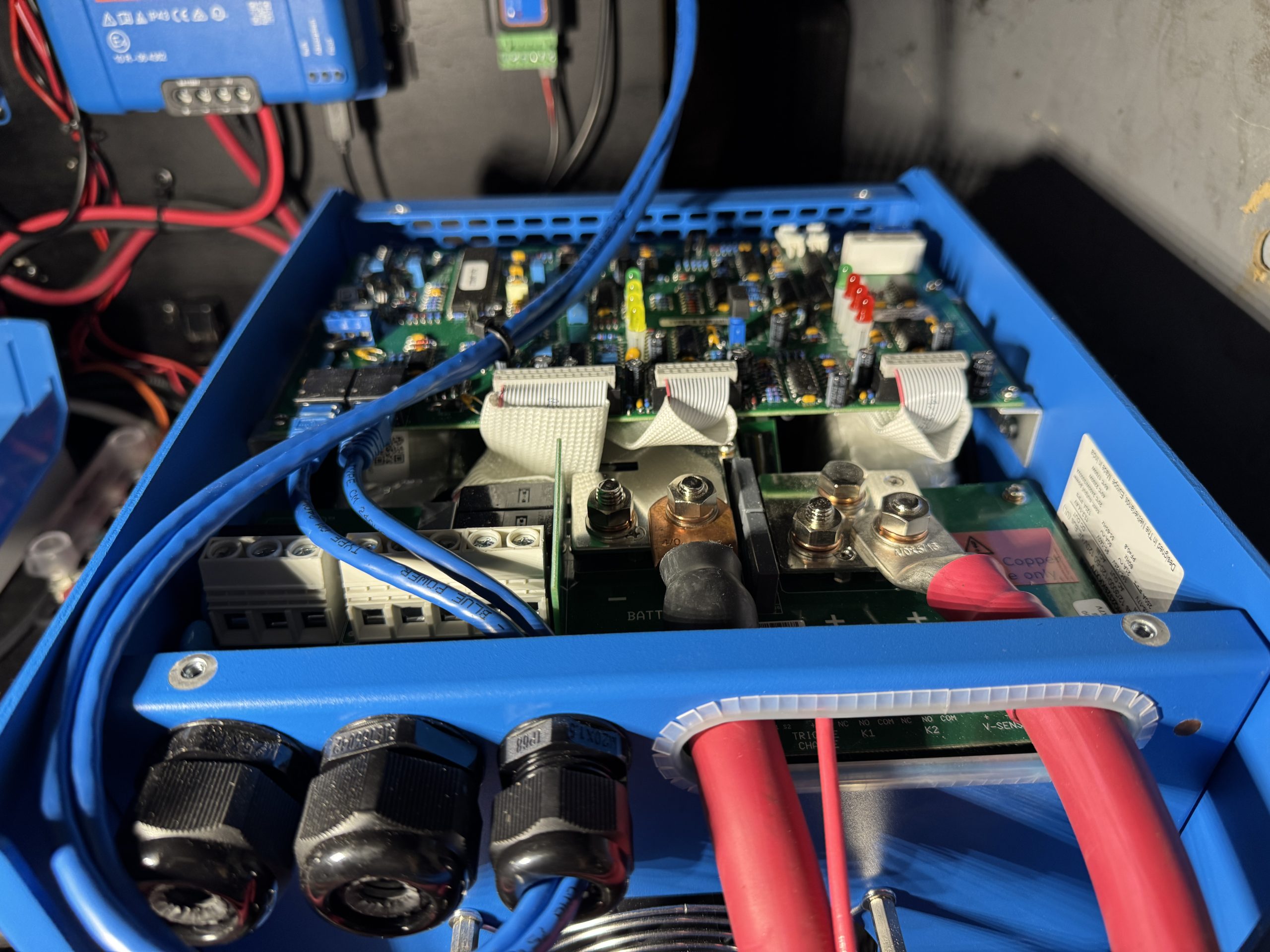
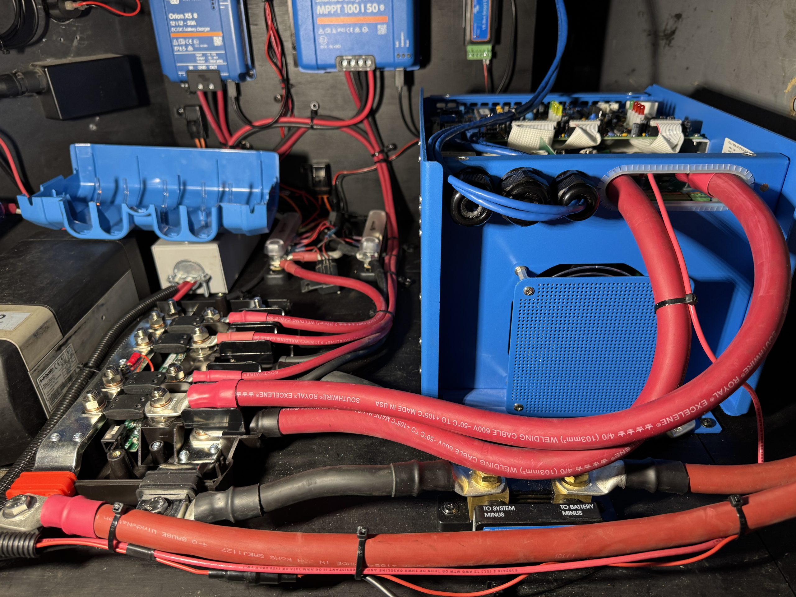
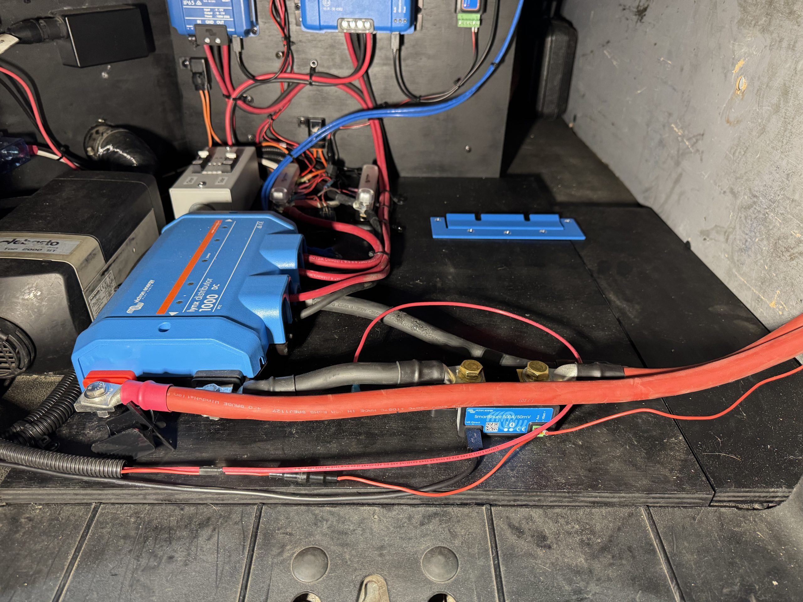
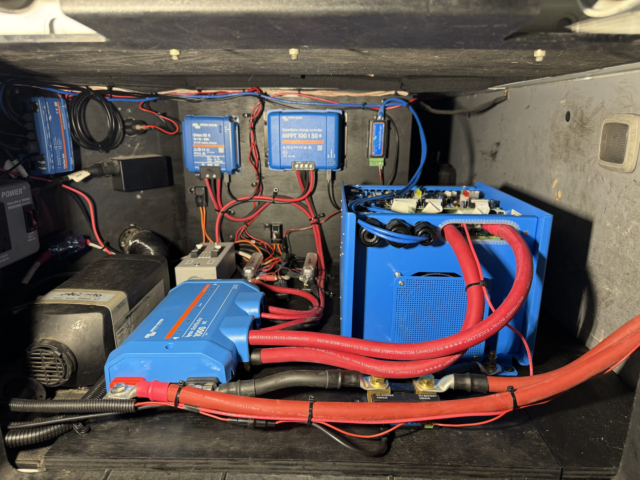
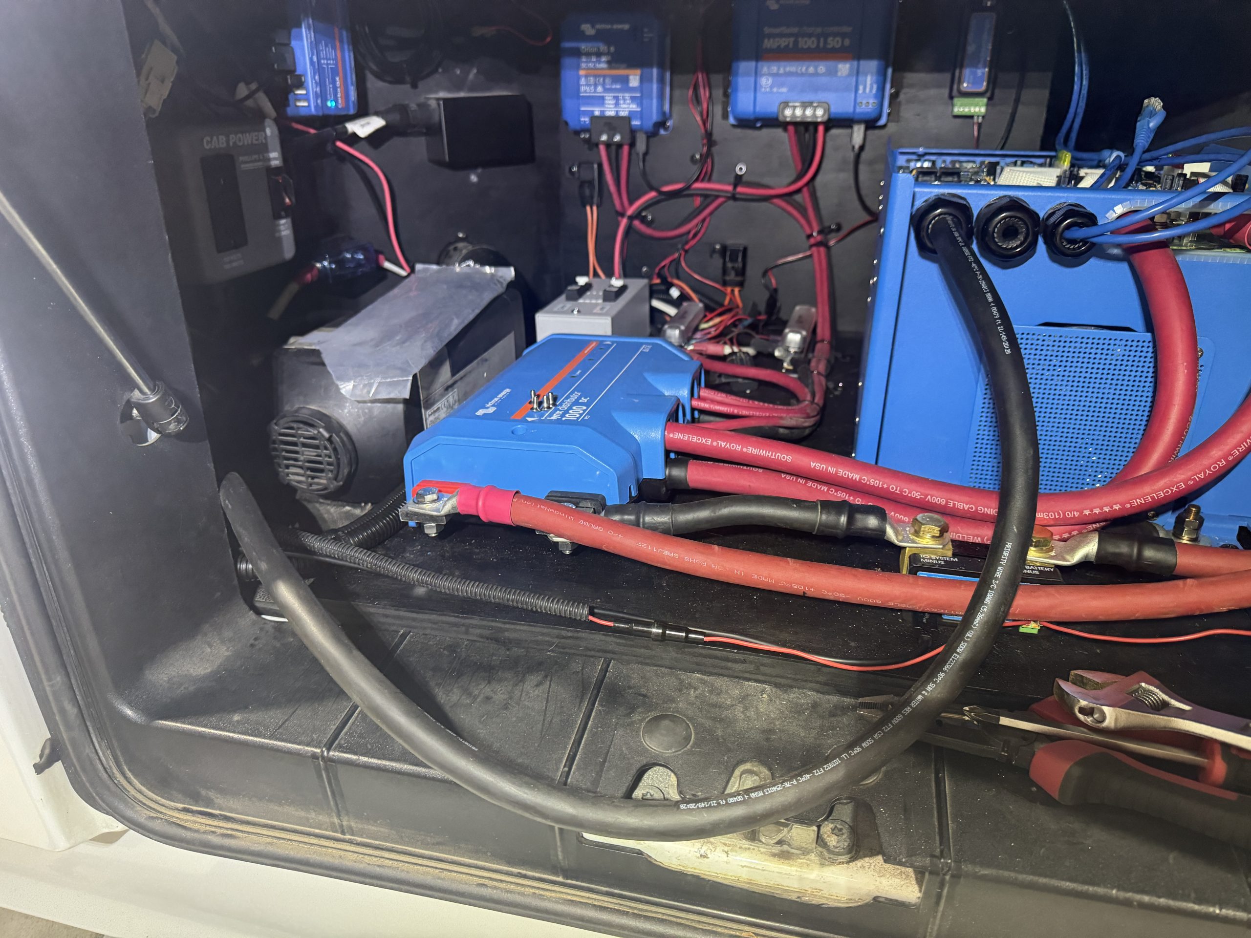
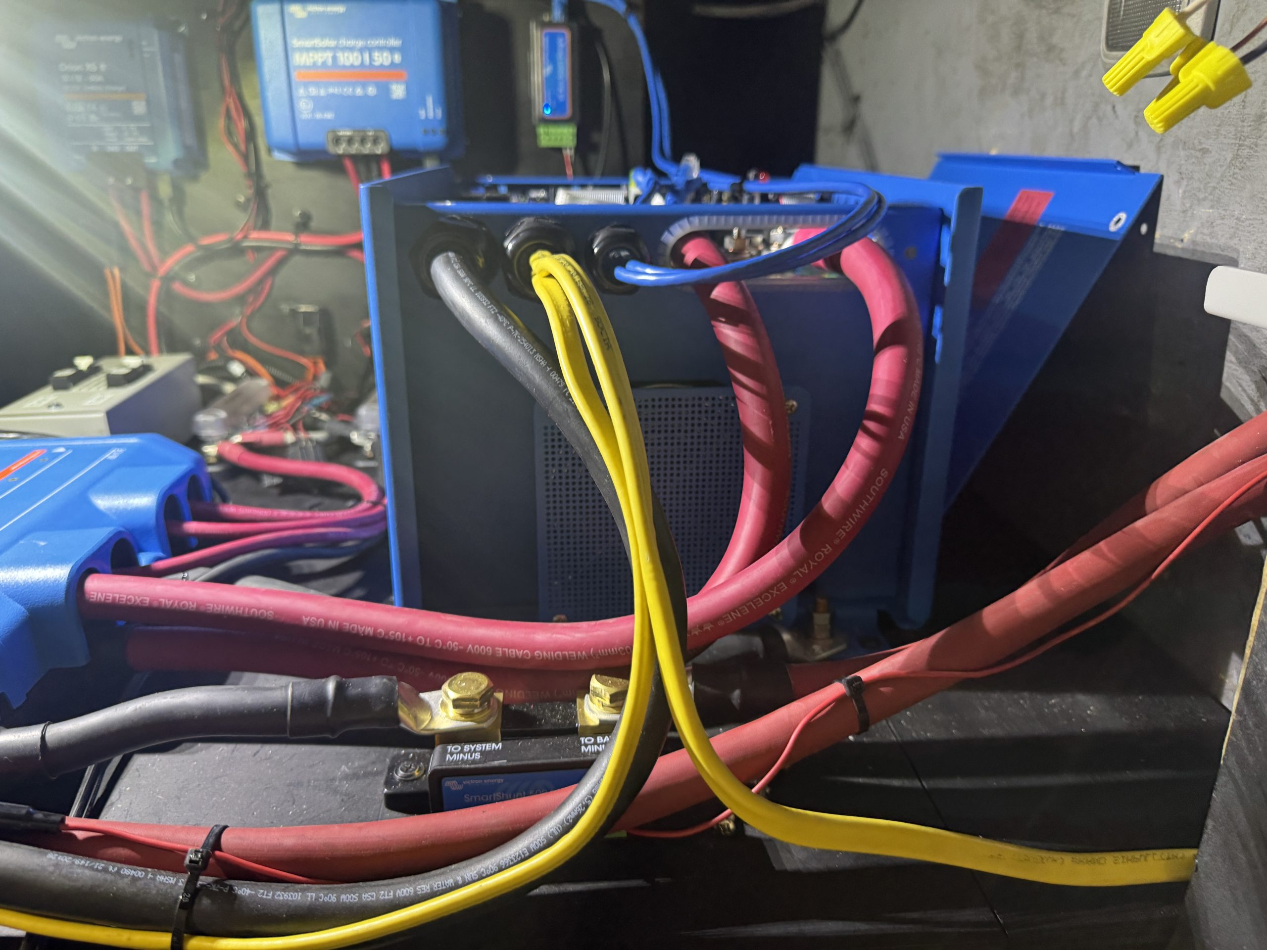
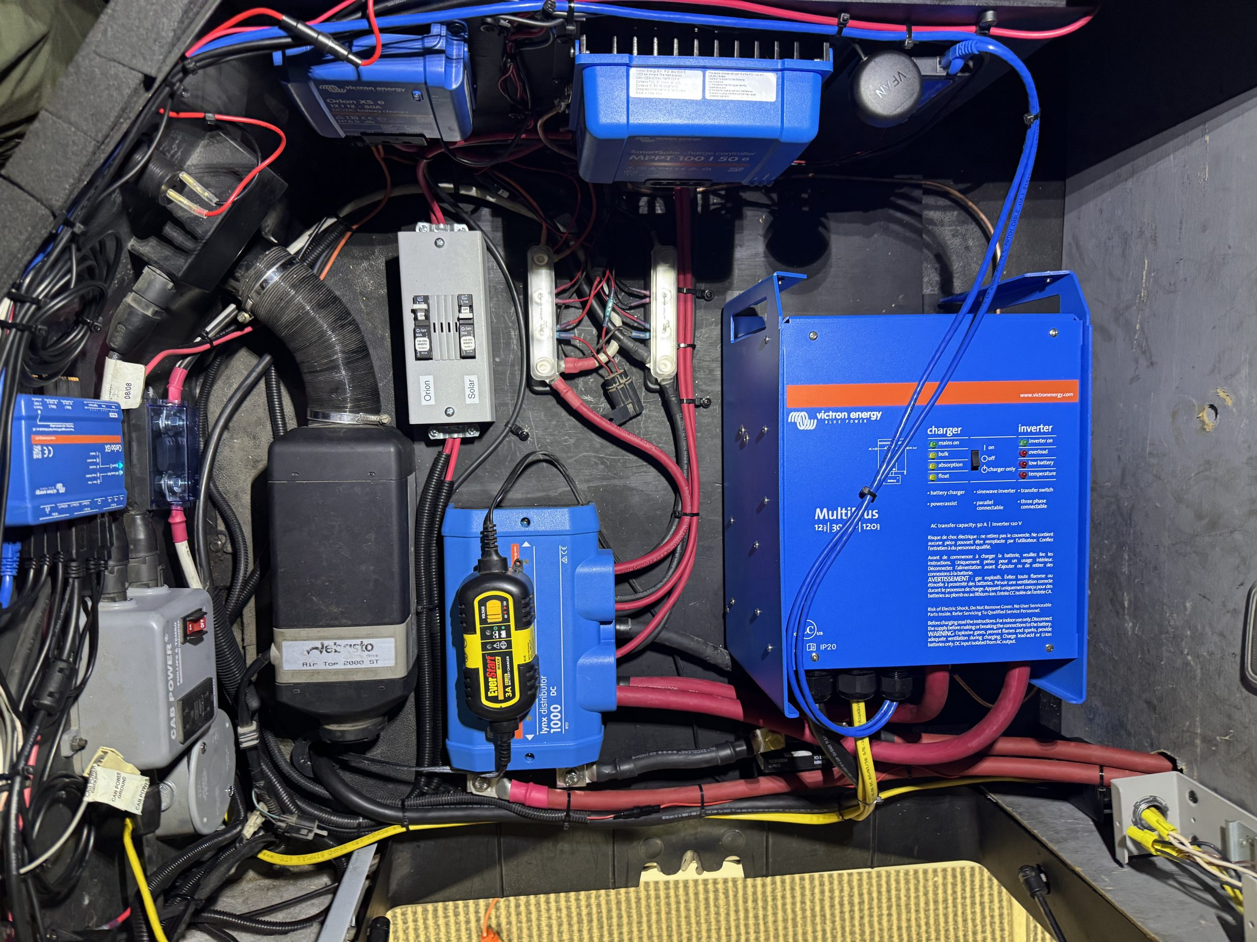
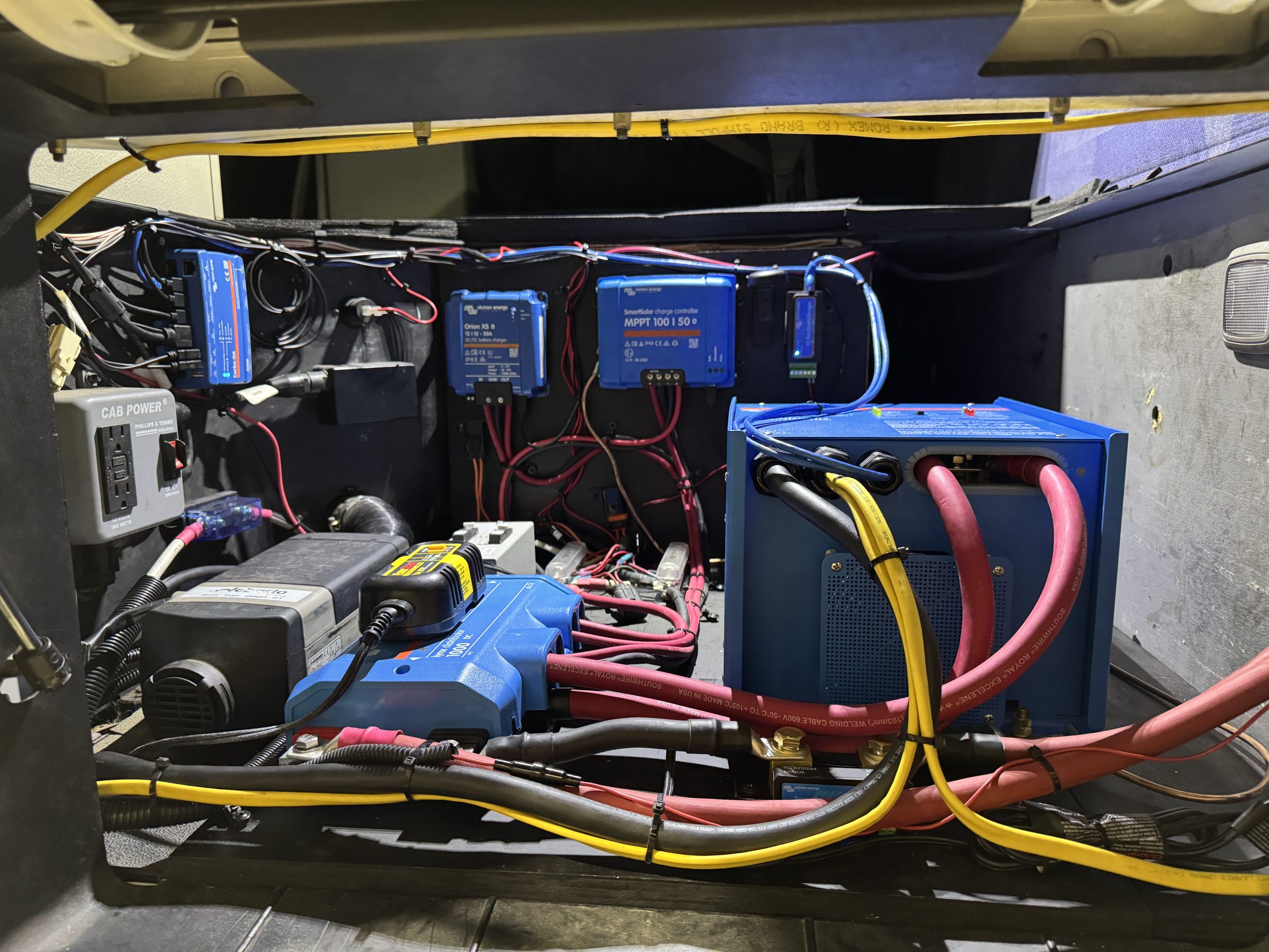
I began by installing some mounting boards in the Jockey box to give me something to which I could secure all the Victron equipment. I used 3/4″ plywood for the mounting boards on the floor and one wall of the compartment. I painted the boards black for aesthetic purposes and began testing equipment layout positions. I settled on installing the Orion XS DC to DC charger and the SmartSolar 100/50 MPPT to the interior center wall of the compartment. I added a Lynx distributor, a 500 amp Smartshunt and the Multiplus inverter charger to the floor of the compartment. I also added a set of Victron 150 amp bus bars to the floor of the compartment to make miscellaneous DC connections for sleeper components easy. Once I was happy with the equipment layout, I started the wiring process.
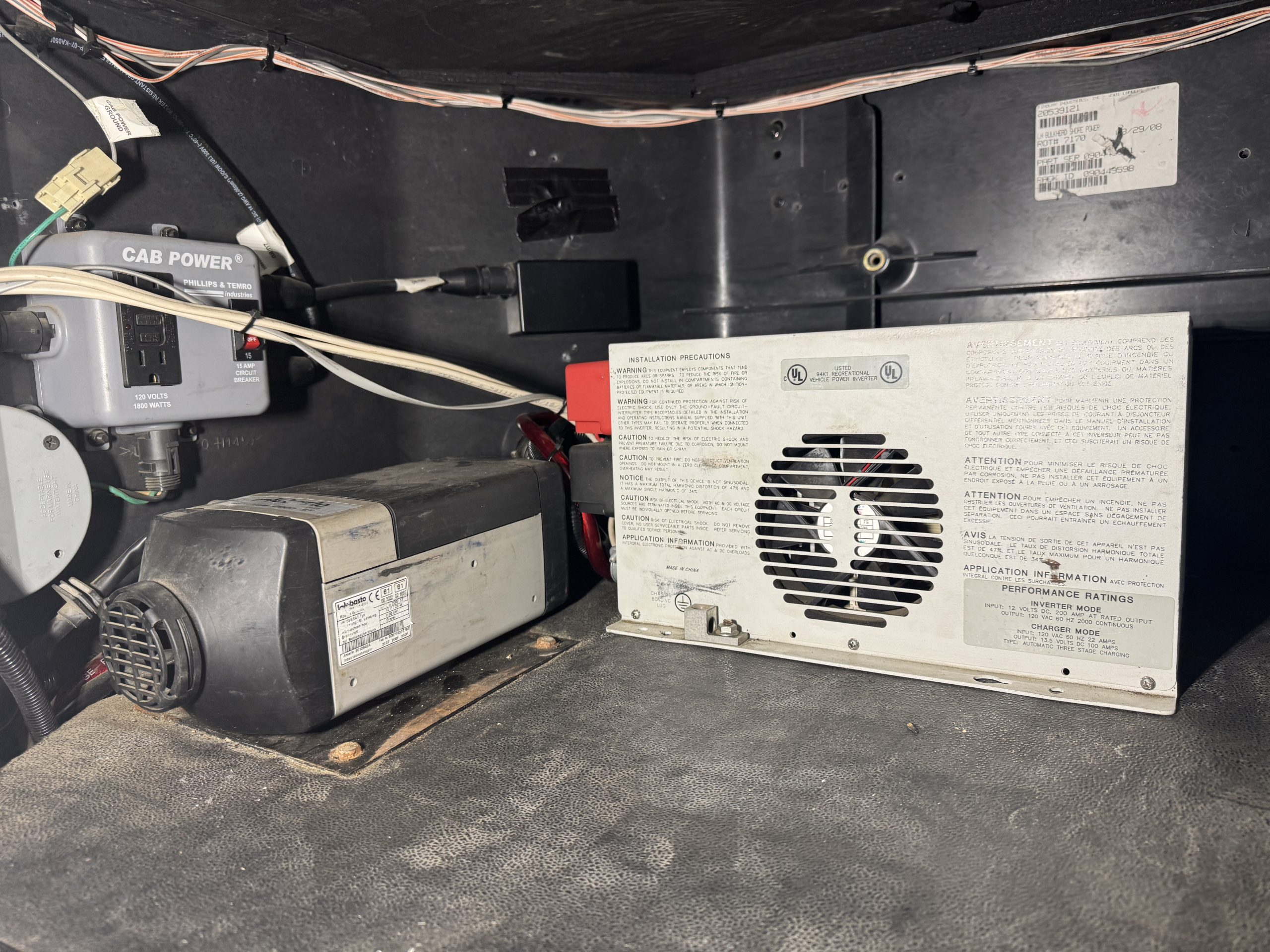
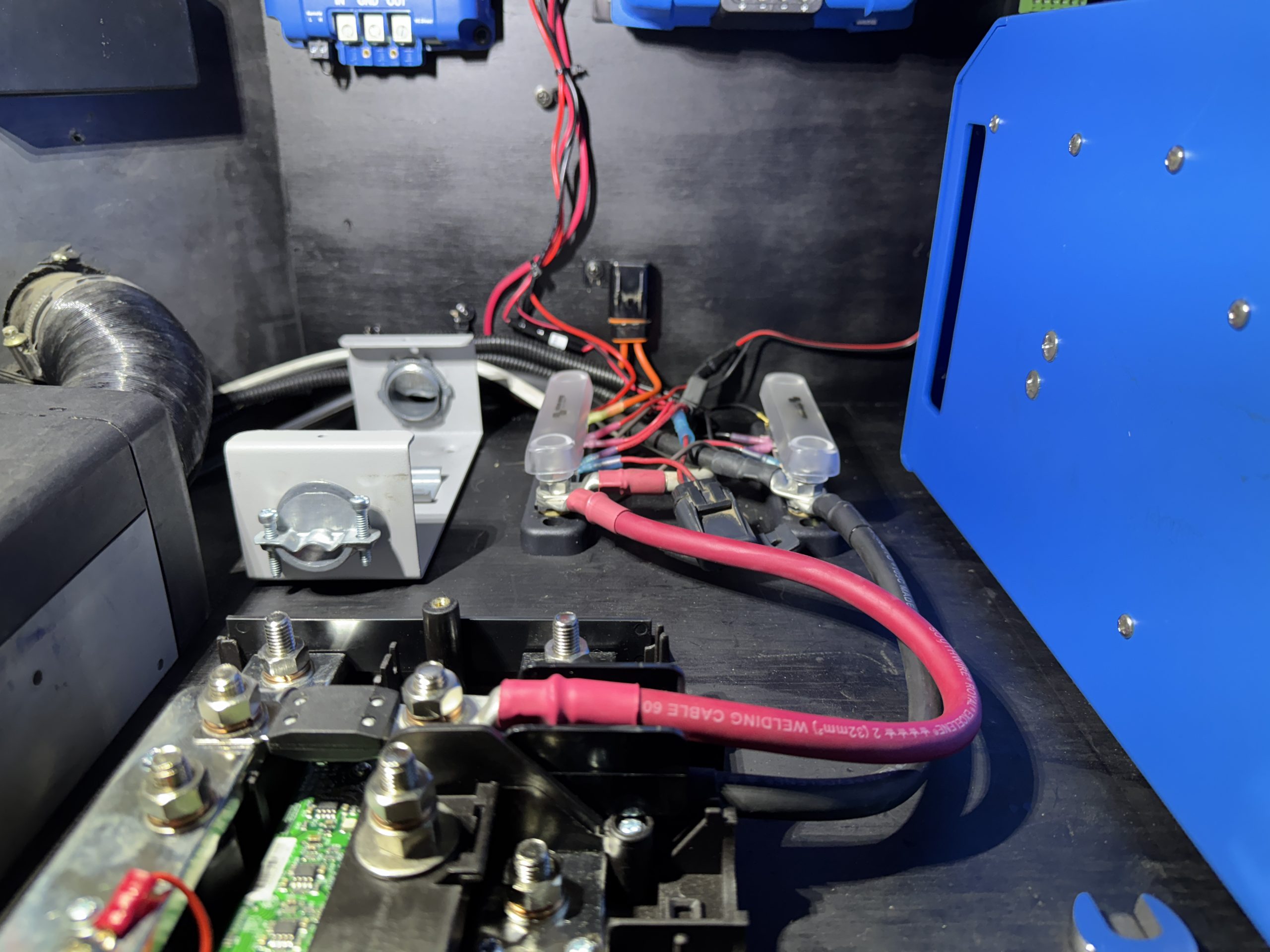
I installed 2 AWG welding cable between the Lynx distributor and the bus bars and fused that circuit with a 100 amp Mega fuse in the distributor. I used these bus bars to provide power to some existing sleeper components and some new items that I added as part of this installation. The Volvo had an OEM DC powered refrigerator. I moved the power supply for the refrigerator from the chassis battery system to the new bus bars so it would be powered from the new Battle Born house battery bank. The Volvo also had a Webasto diesel fired heater that was wired to the chassis batteries. I moved this circuit over to the bus bars as well to allow the Battle Born house battery bank to power it. The Volvo has a custom built hauler bed that had a DC circuit run to the rear, driver’s side, storage compartment by the bed builder. This is the compartment where the waste water tank and access to the freshwater tank fill are located. The bed builder installed a water pump (to pump water from the on board freshwater tank) and a positive and negative DC bus in this compartment to power a macerator pump. This circuit was originally wired to the chassis batteries. I moved this circuit to the new bus bars as well. I added a Victron Mega fuse holder and a 60 amp Mega fuse in the positive wire of this circuit for circuit protection after the bus bars.
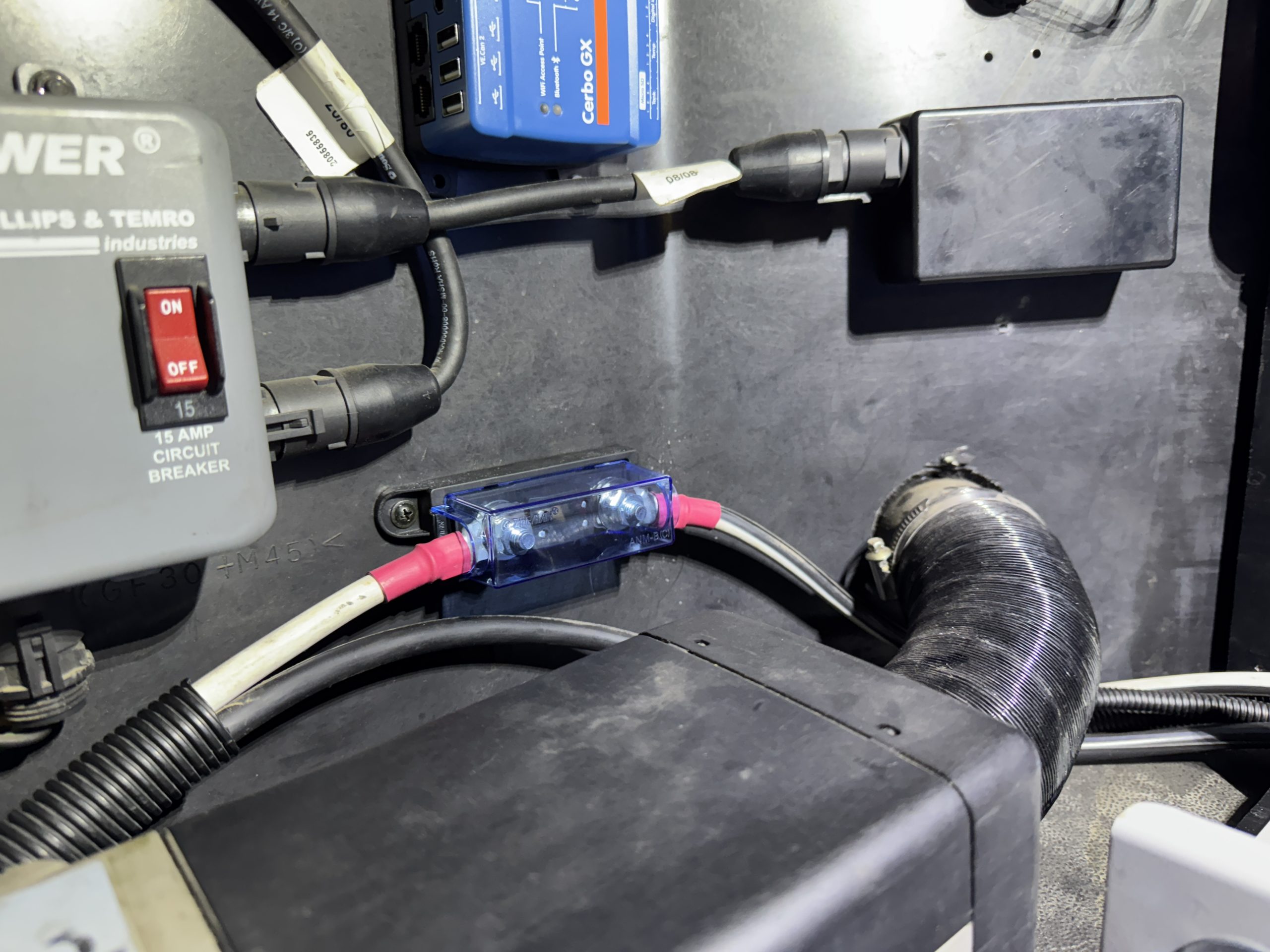
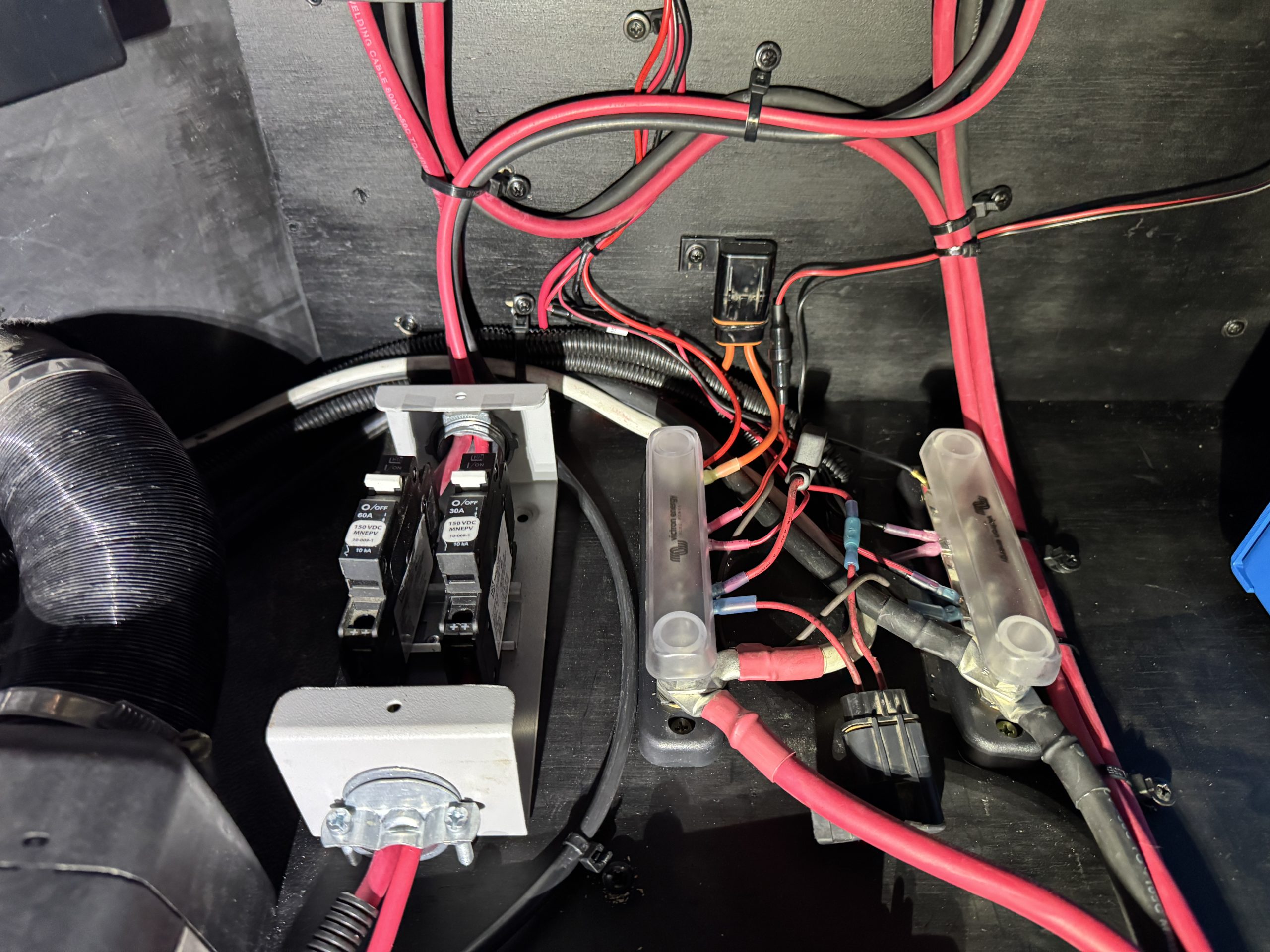
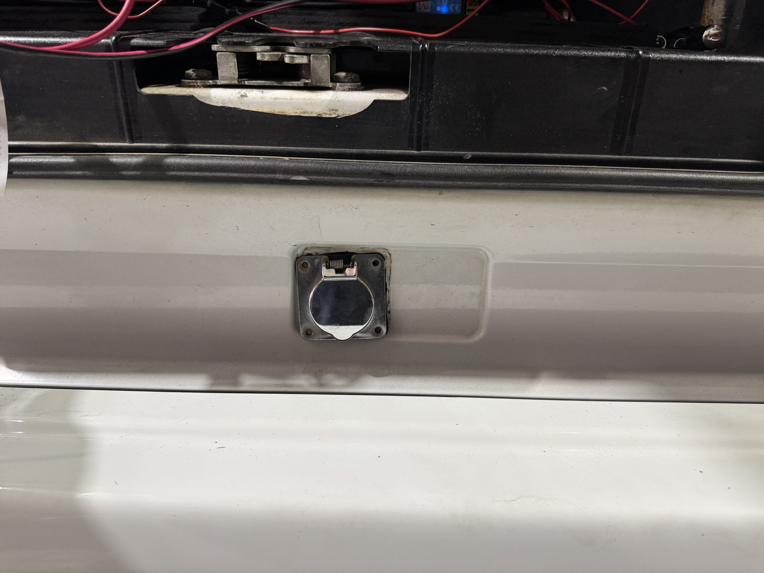
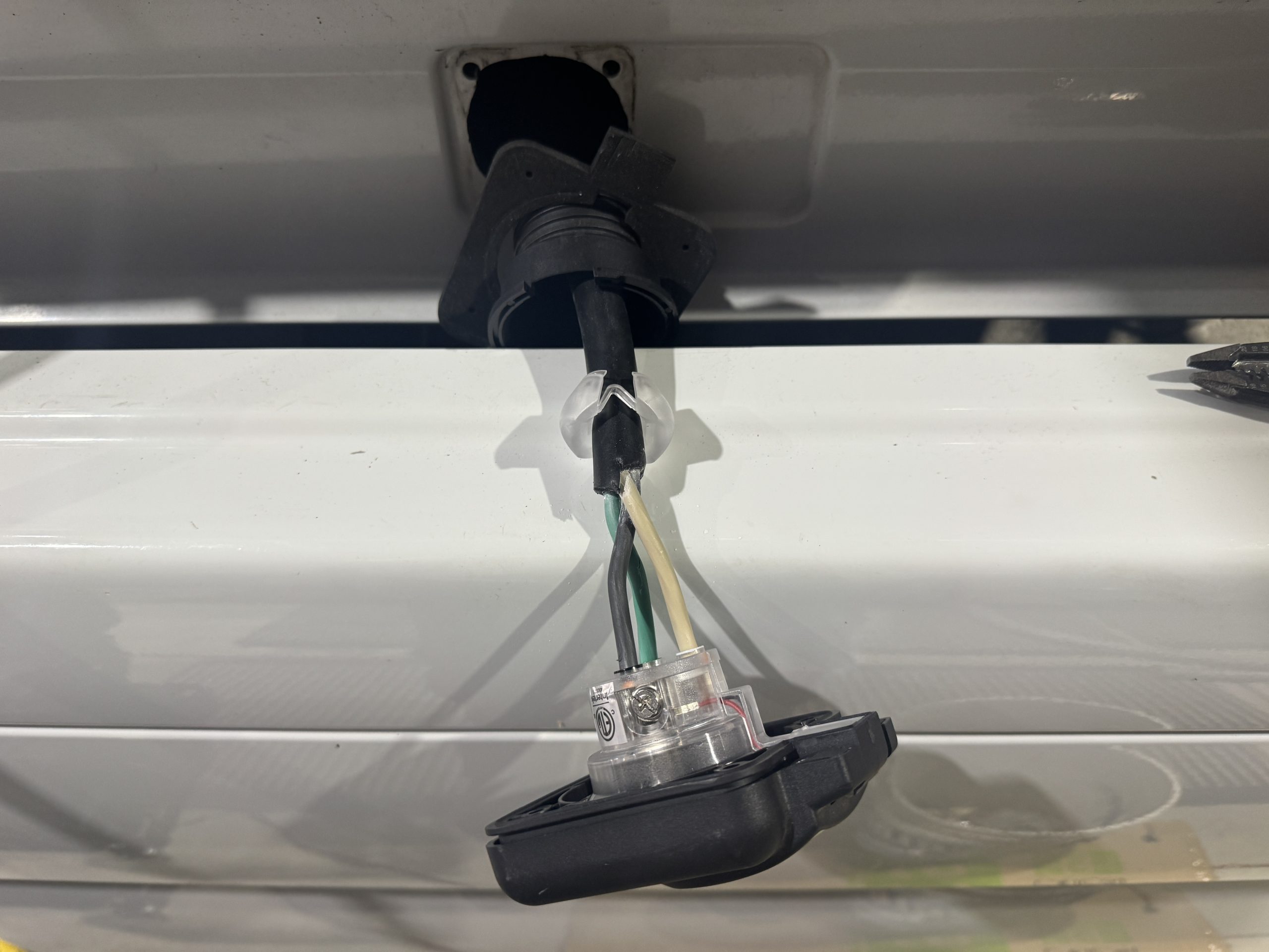
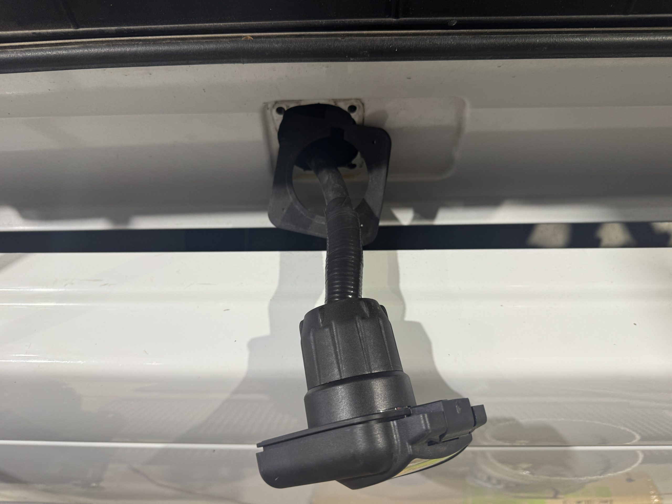
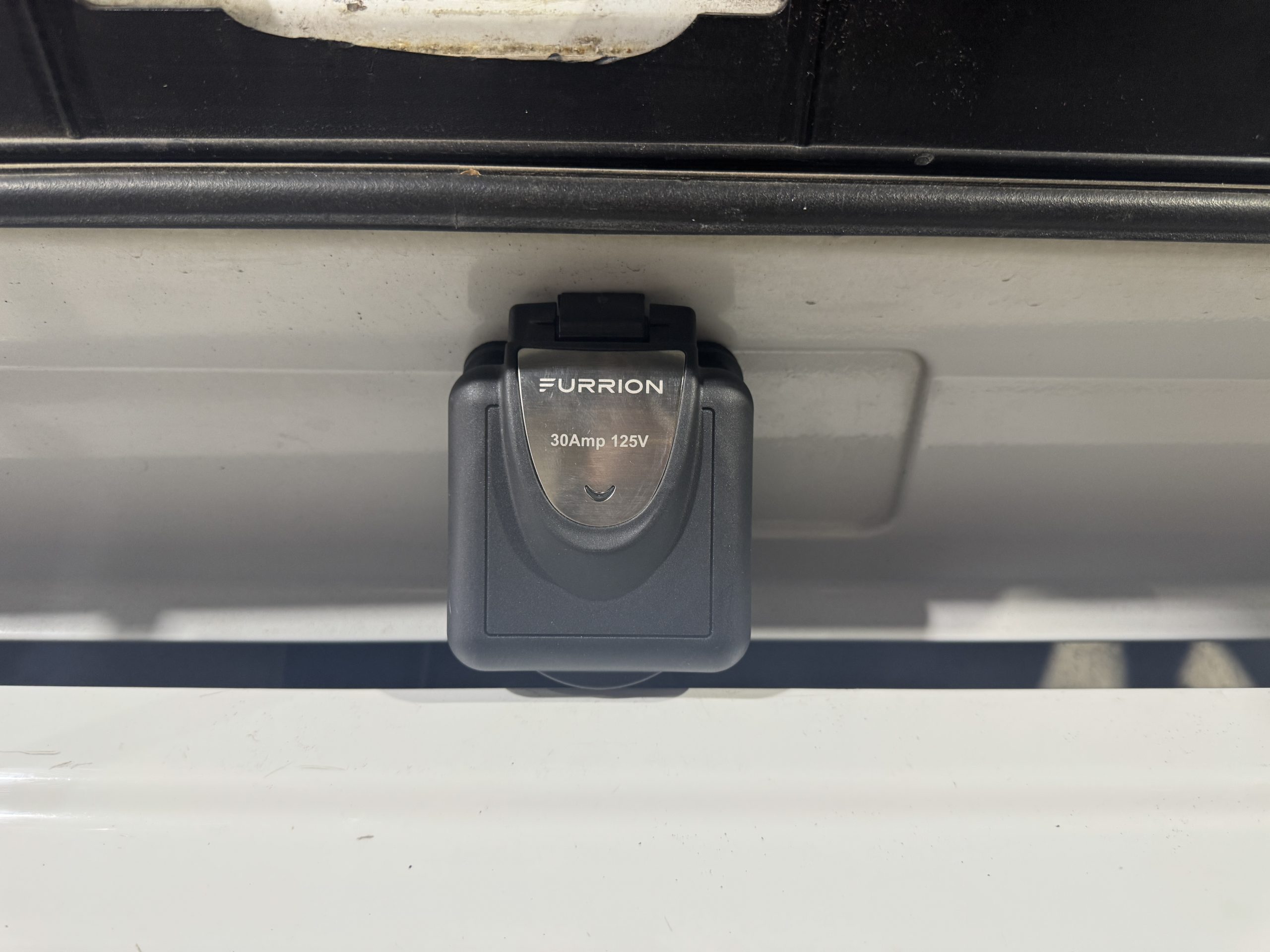
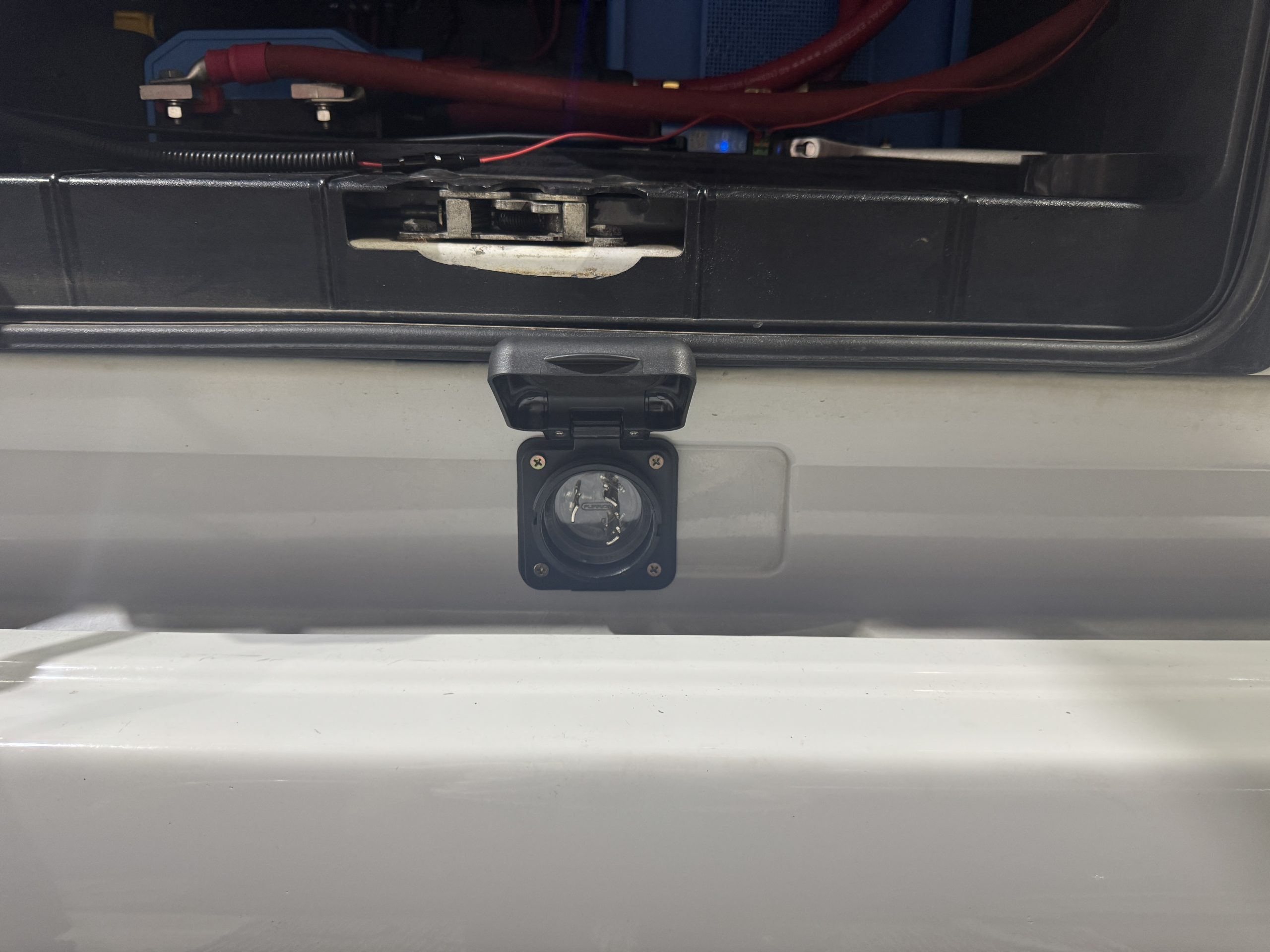
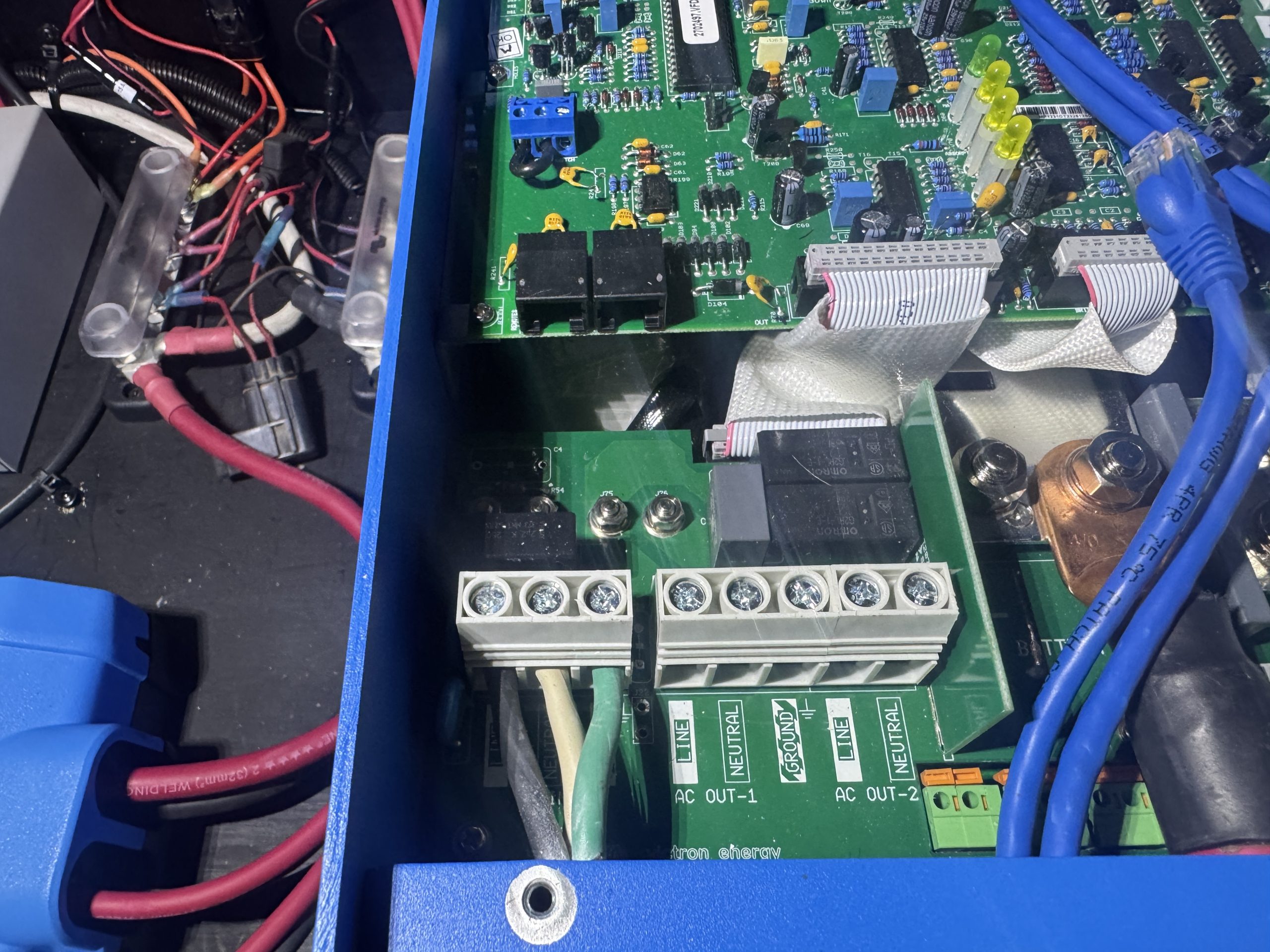
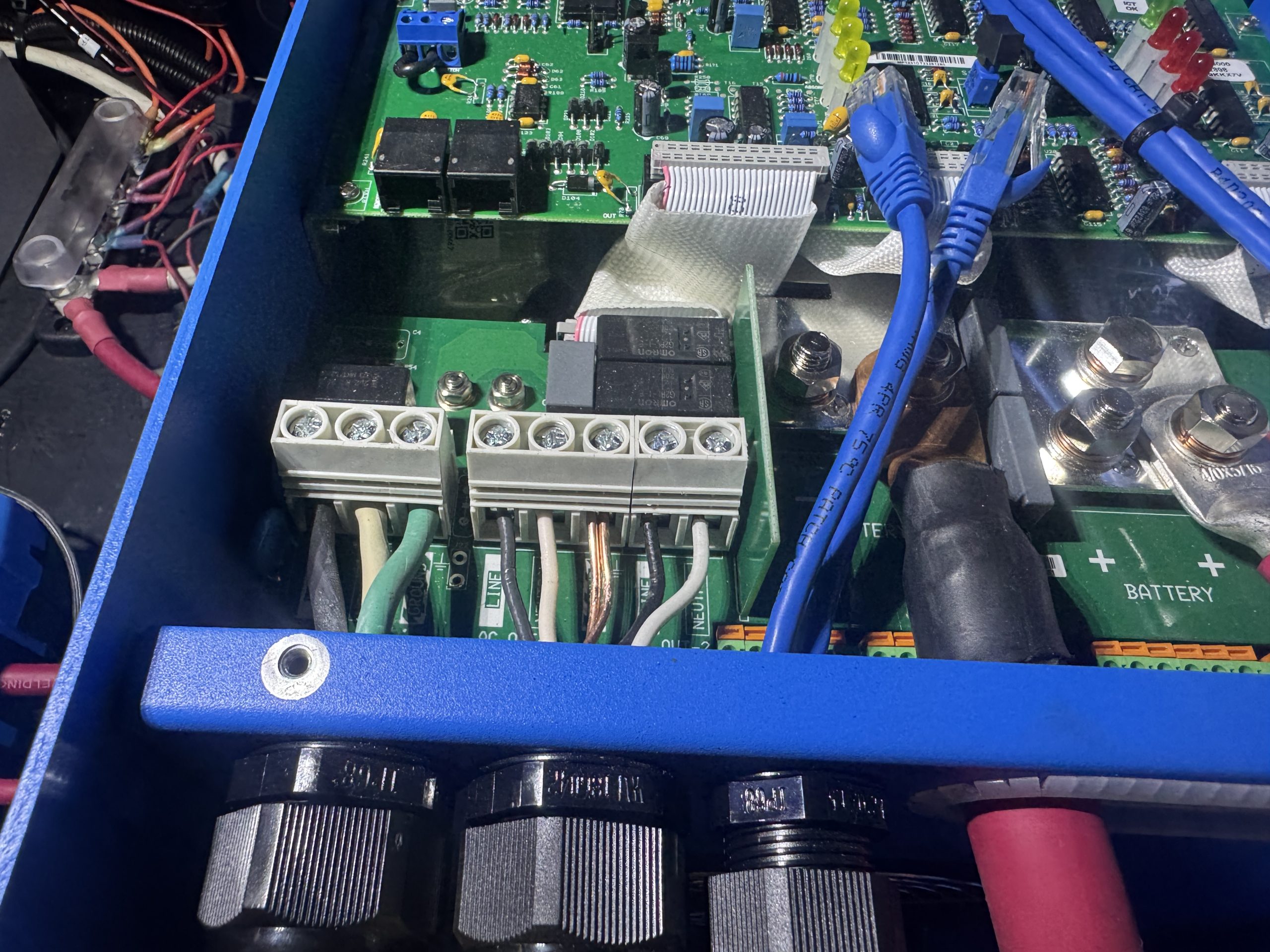
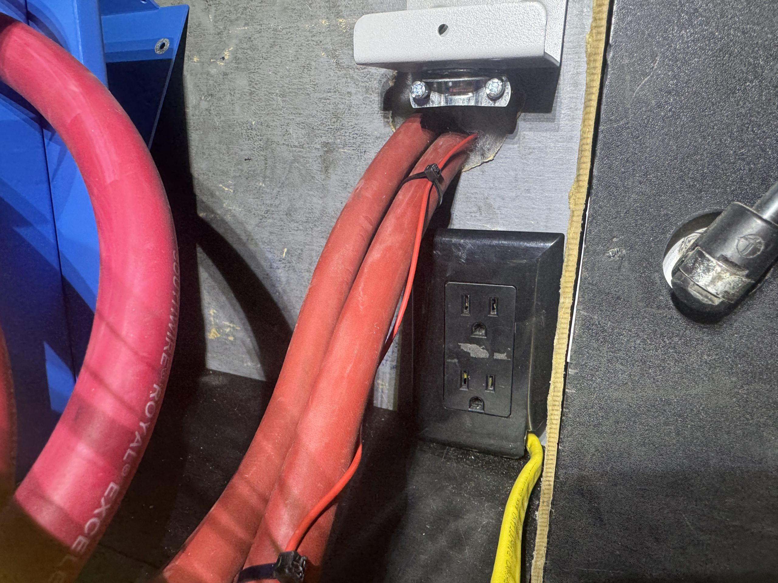
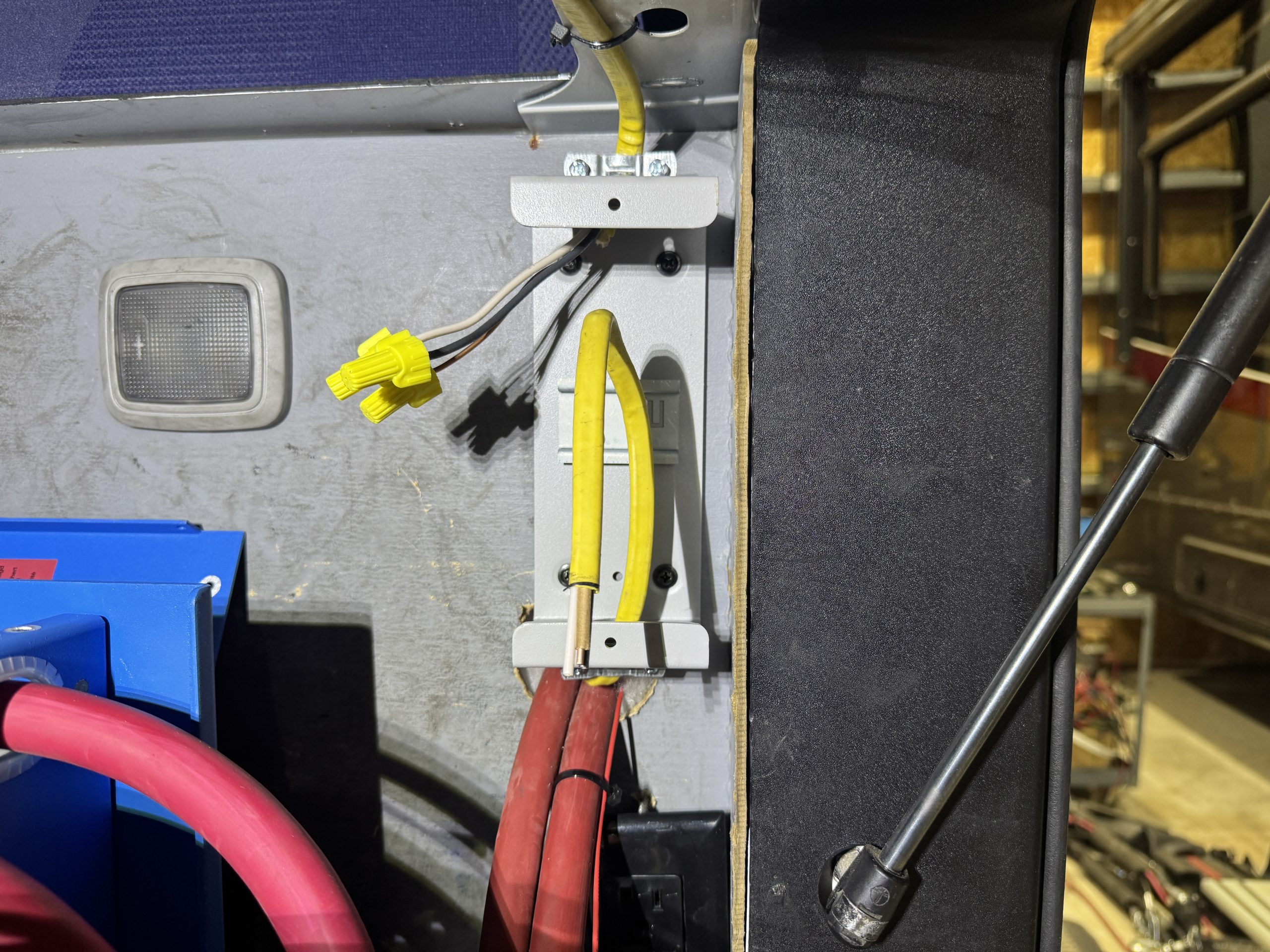
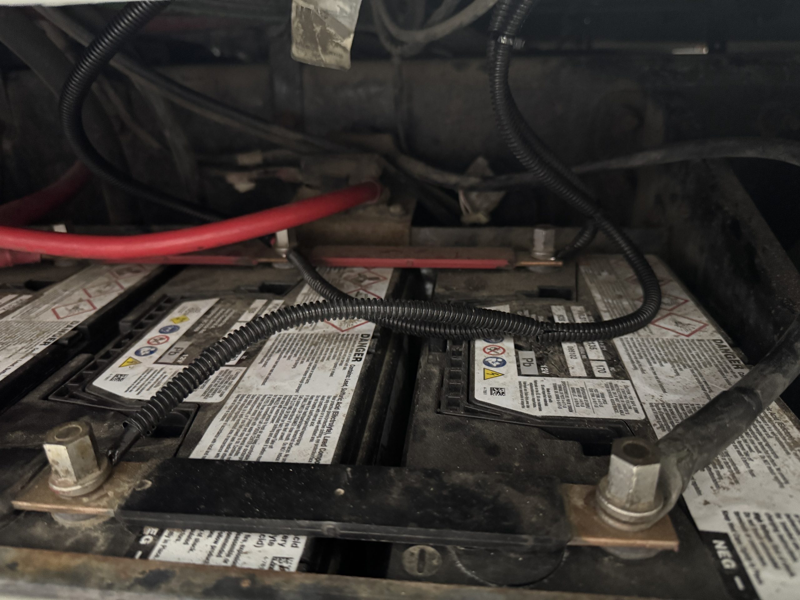
I wired the output of the Orion XS to the Lynx distributor with 6 AWG welding cable. I fused this connection with a 60 amp Mega fuse. I wired the input to the Orion XS with 6 AWG welding cable as well. This cable connected to a positive terminal on the chassis battery bank and went through a 60 amp MNEPV DC circuit breaker before connecting to the input of the Orion XS. I wired the battery side of the SmartSolar 100/50 MPPT to the Lynx distributor with 6 AWG welding cable and fused that circuit with a 60 amp Mega fuse. I wired the solar input of the MPPT with 10 AWG PV cable and ran this cable out the floor of the Jockey box to the back of the sleeper. I terminated these cables with MC4 connectors in preparation to later connect the solar panels to the solar controller easily. The positive cable in this circuit is protected by a 30 amp MNEPV DC circuit breaker. I wired 4/0 welding cable into the fourth position of the Lynx distributor for the Multiplus connection and fused this circuit with a 400 amp Mega fuse. I installed 4/0 welding cable between the exposed negative end connection of the Lynx distributor and the load side of the SmartShunt. I utilized the Aux 1 input of the SmartShunt to connect a voltage sense wire for the chassis batteries so I could monitor their voltage via the shunt and the Victron system. The original inverter had 12 gauge wire run from an external 120 volt socket to the inverter AC input. I upgraded this original 120 volt socket to an RV style twist lock 30 amp power cord receptacle. I replaced the 12 AWG wire with 10 AWG SOOW cable and eventually wired this to the AC Input of the Multiplus. I connected the AC Out 1 connection of the Multiplus to the Volvo factory AC distribution system with 12/2 Romex. I added a single 120 volt receptacle to the Jockey box rear wall and wired this receptacle to the AC Out 2 connection in the Multiplus. By default, this connection is only powered when an AC input is detected and passed through the Multiplus. I had a smart battery maintainer that I permanently connected the outputs of to the chassis batteries with ring terminals. I then plugged the AC power cord for the maintainer into the new receptacle powered by the Multiplus AC Out 2 circuit. This way, when I plug the Volvo into a shore power source, the Multiplus will charge the house battery bank and pass power through the AC Out 2 connection to power the battery maintainer. This will keep the chassis batteries charged, as well as the new Battle Born house battery bank, with a single shore power connection. I mounted the battery maintainer to the Lynx distributor cover with double sided tape.
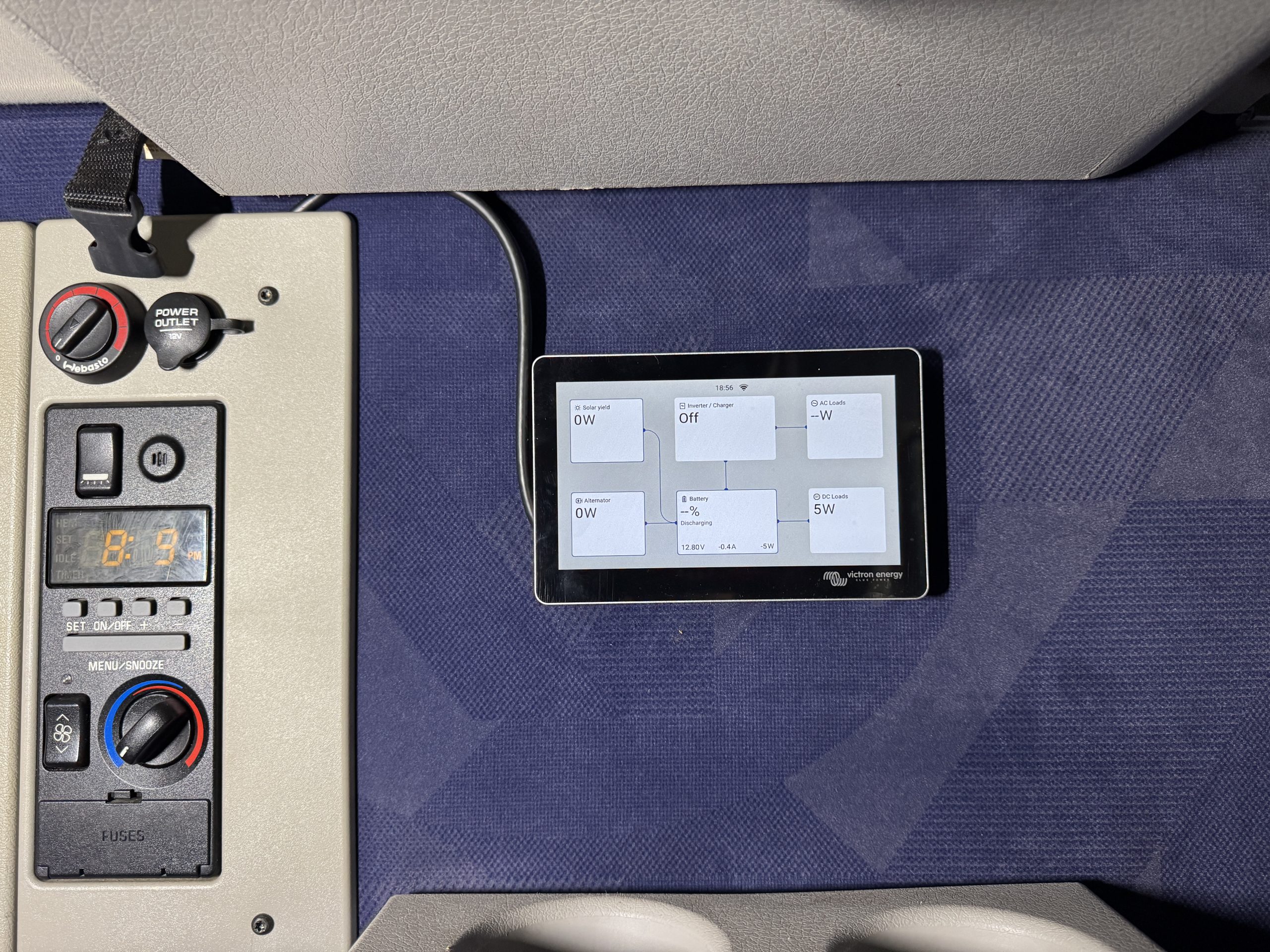
Once I had the main connections to the Lynx distributor completed, I installed a Cerbo GX MKII on the front wall of the Jockey box and connected all the Victron devices with the appropriate data cables (VE Direct and RJ45). I connected the Cerbo power wires to the Victron bus bars for power. I connected a GX Touch 70 screen to the Cerbo and mounted the screen on the wall of the sleeper behind the driver’s seat for convenient access. I also installed a VE Bus Smart Dongle to give the Multiplus Bluetooth connectivity with the Victron Connect app and mounted it to the interior center wall of the compartment. I connected dongle power wires to the VIctron bus bars for power.
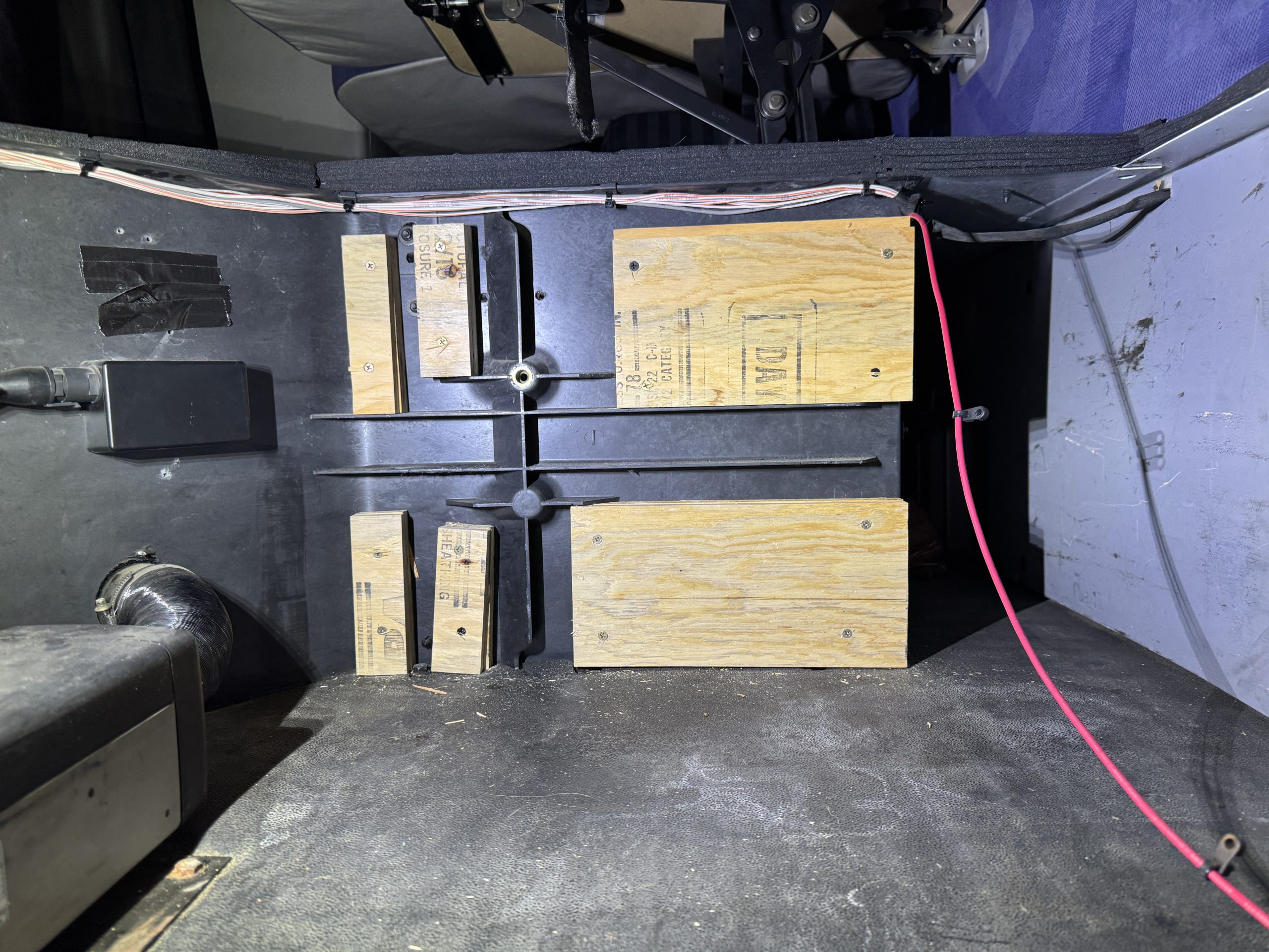
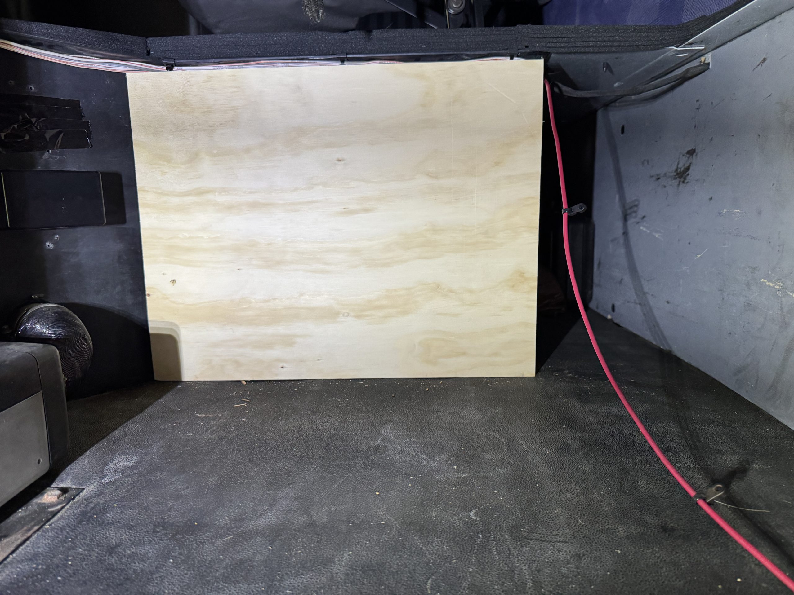
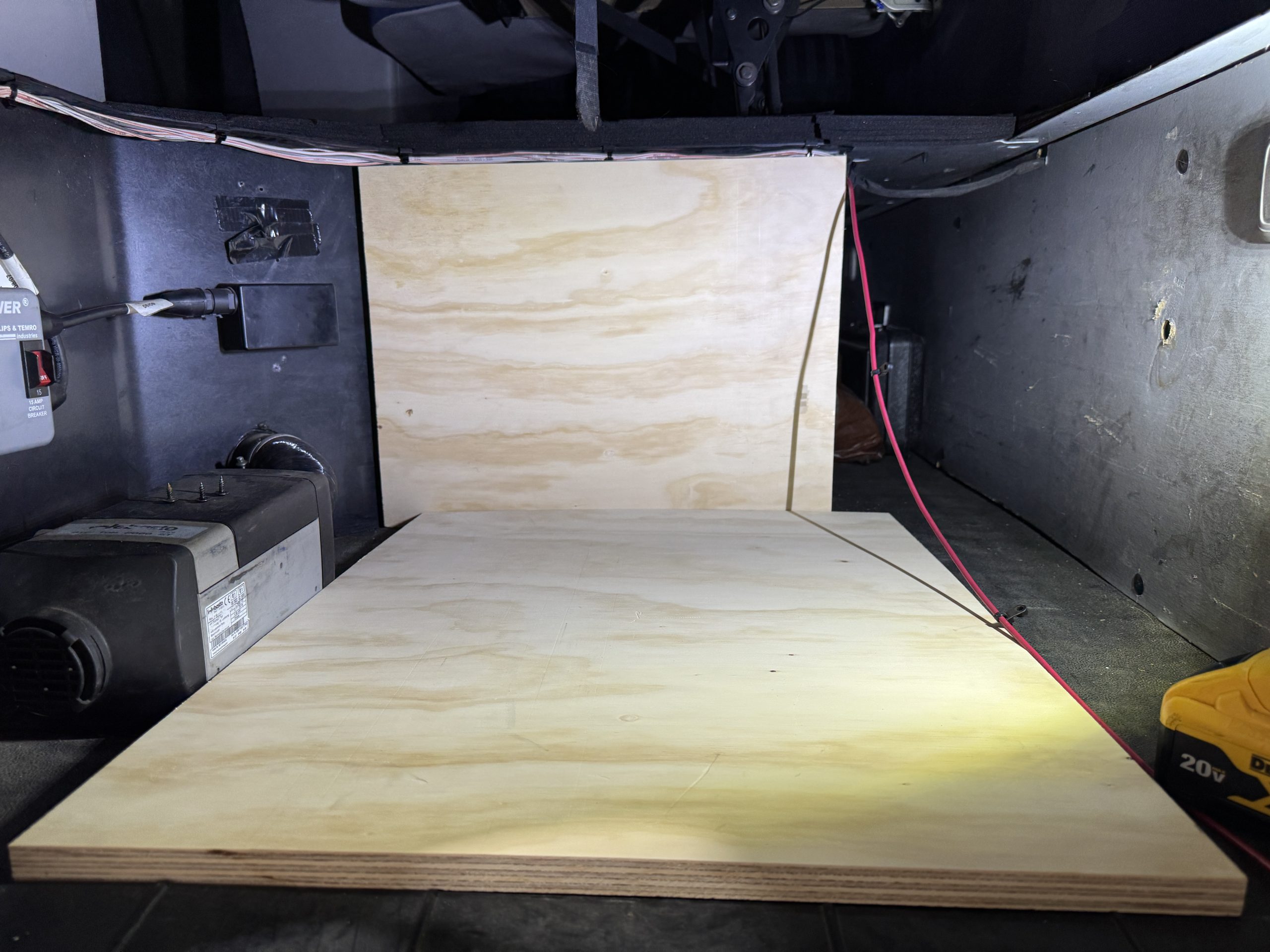
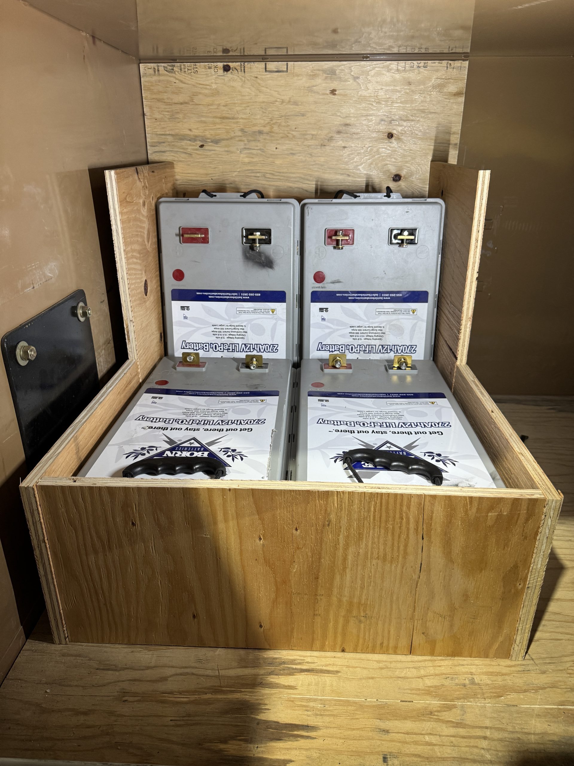
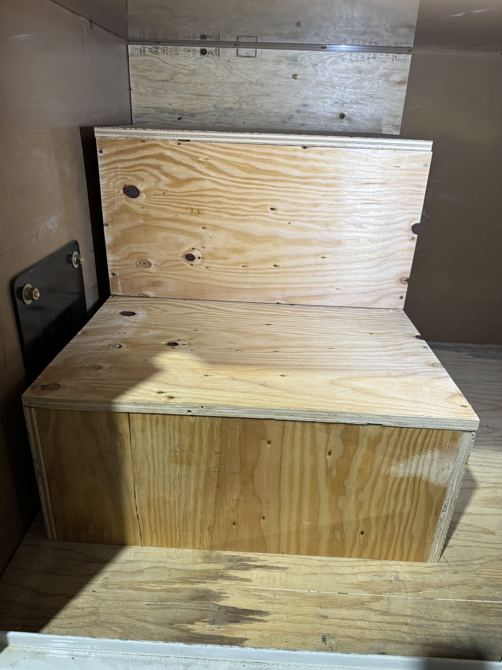
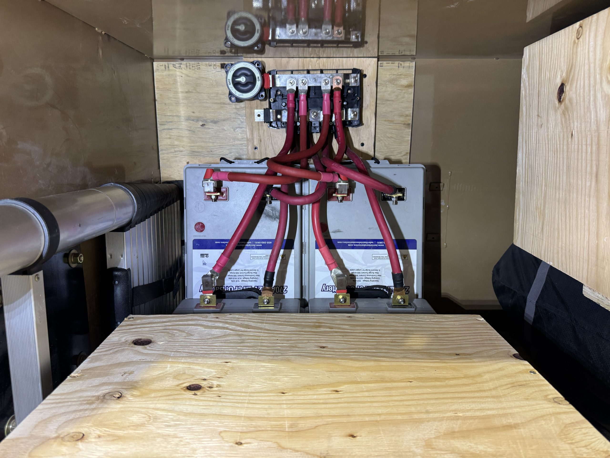
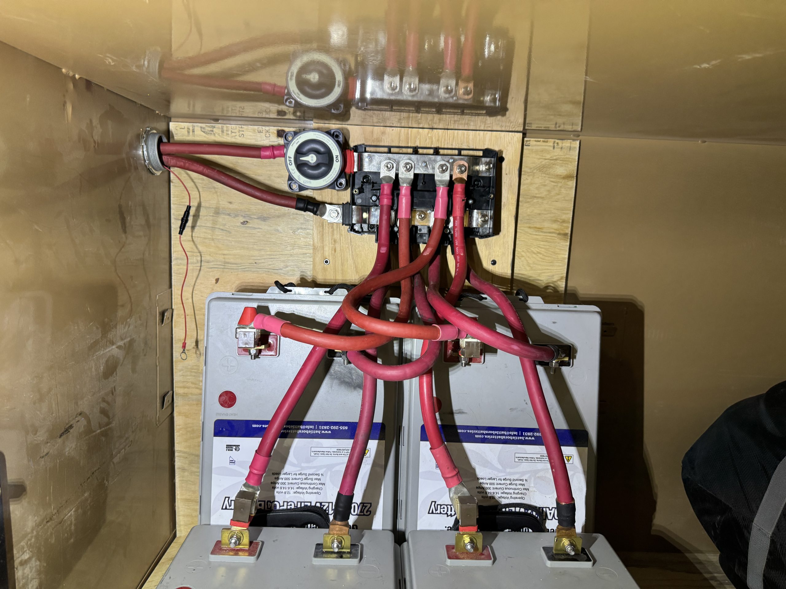
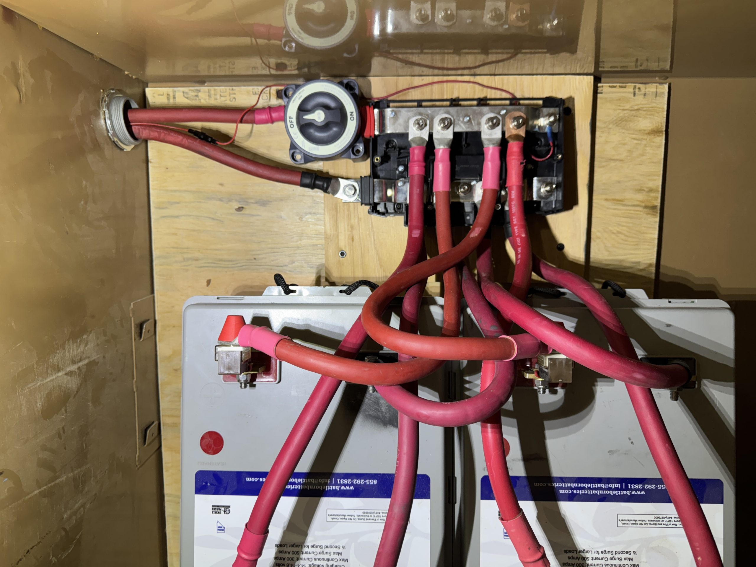
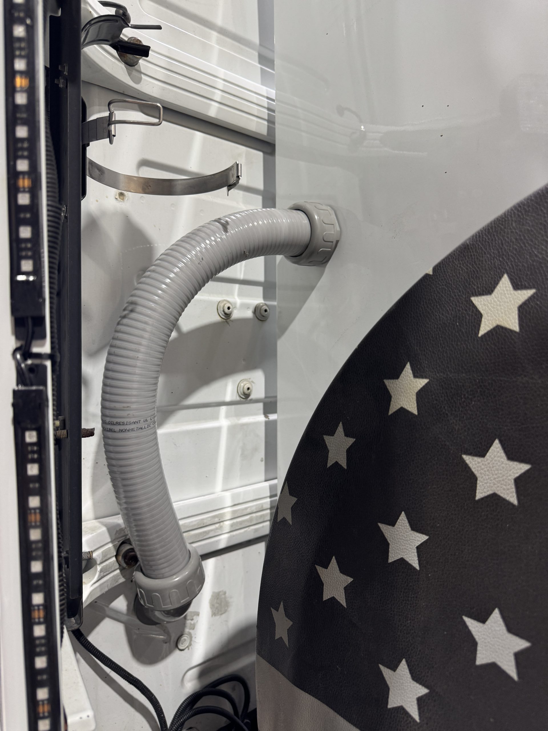
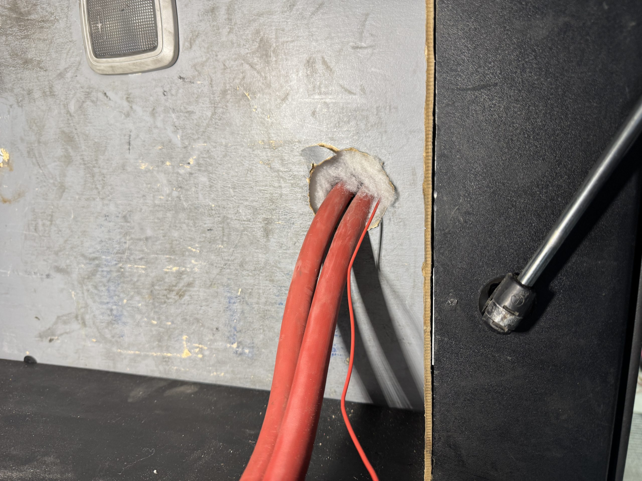
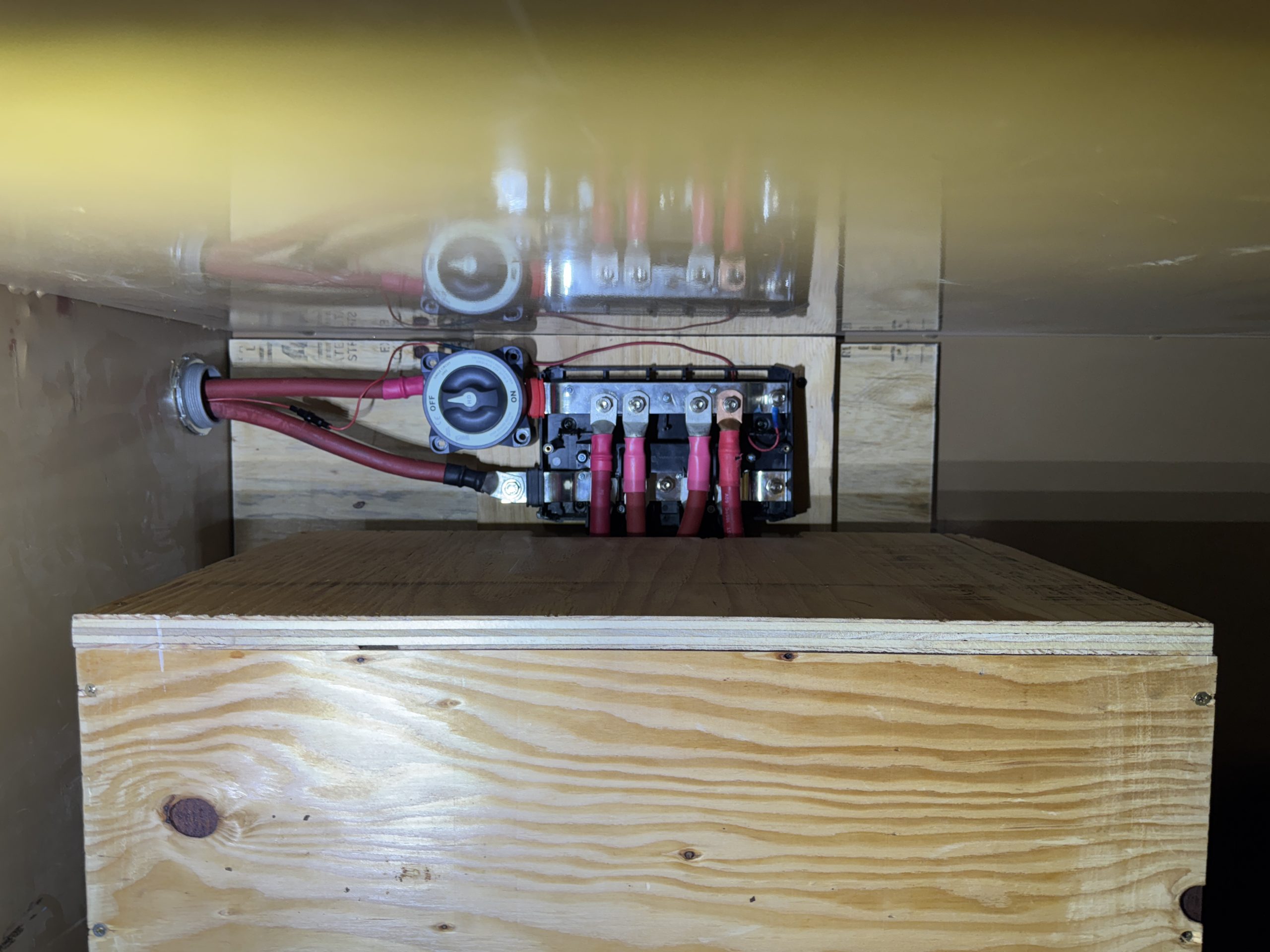
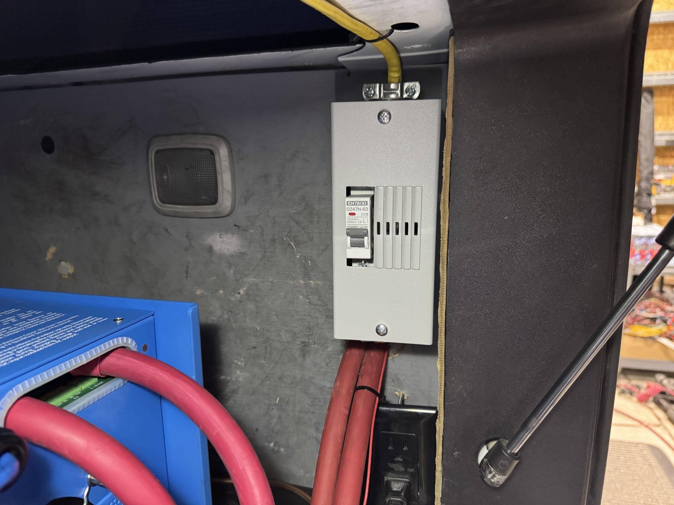
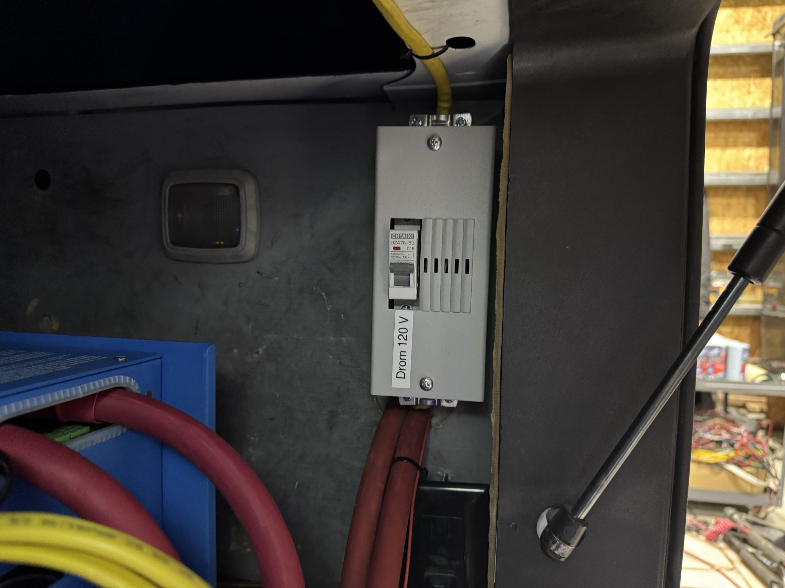
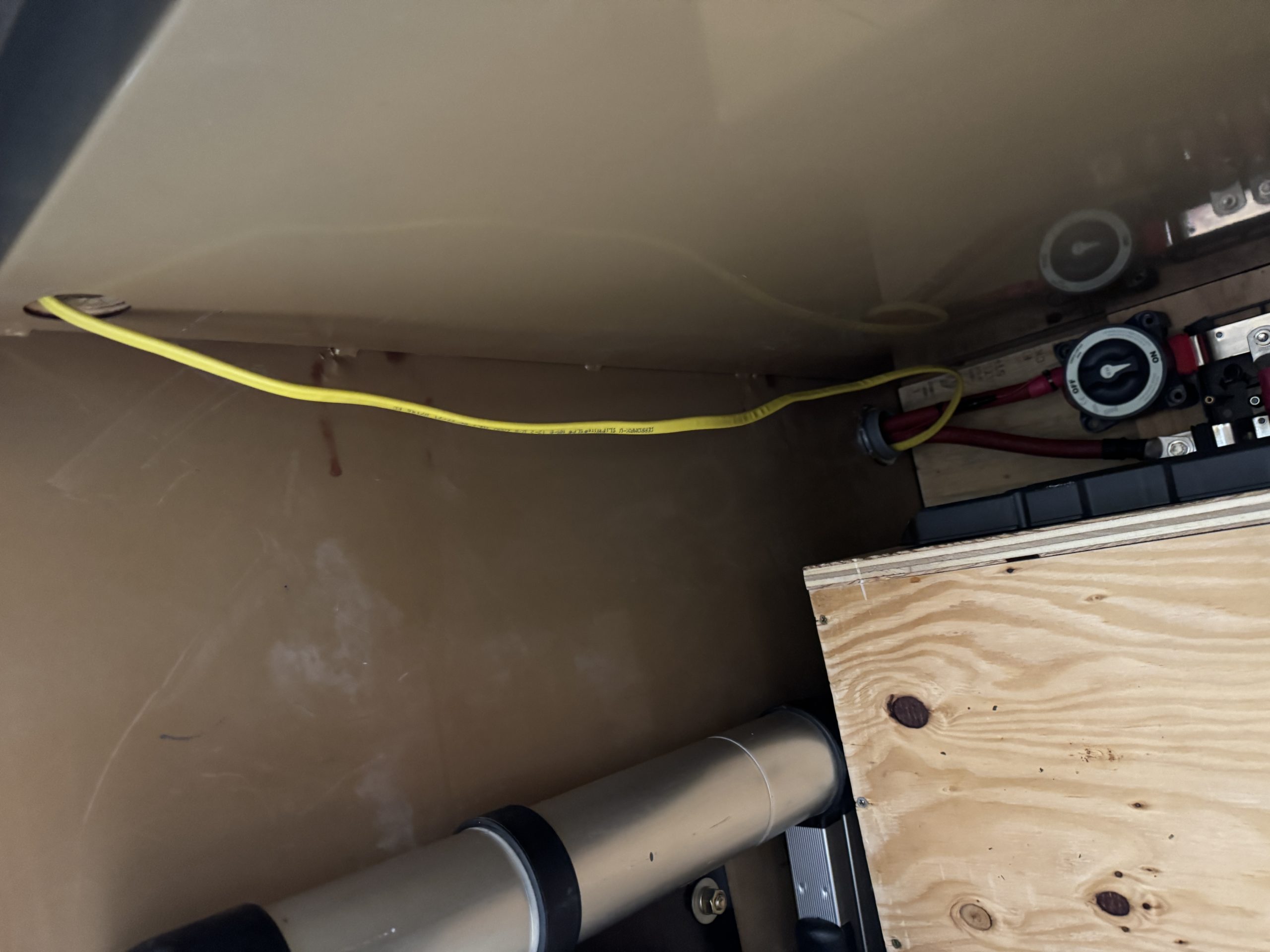
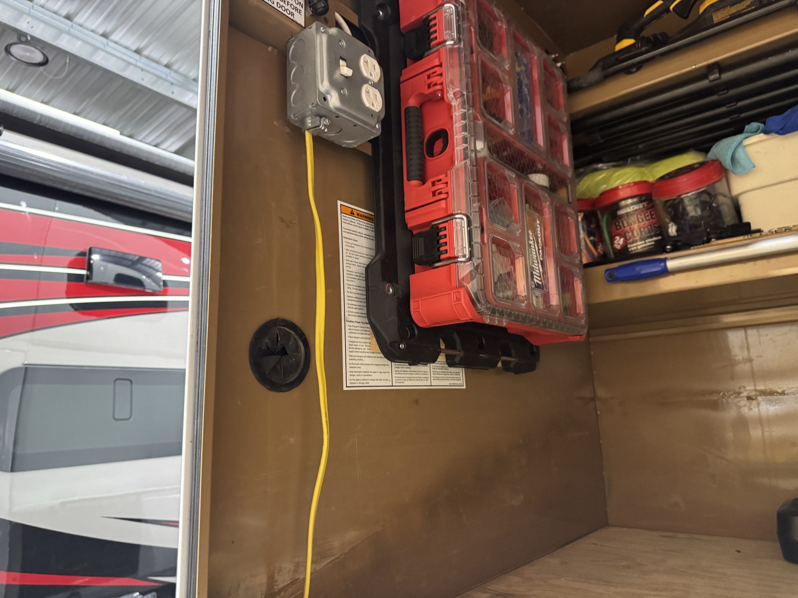
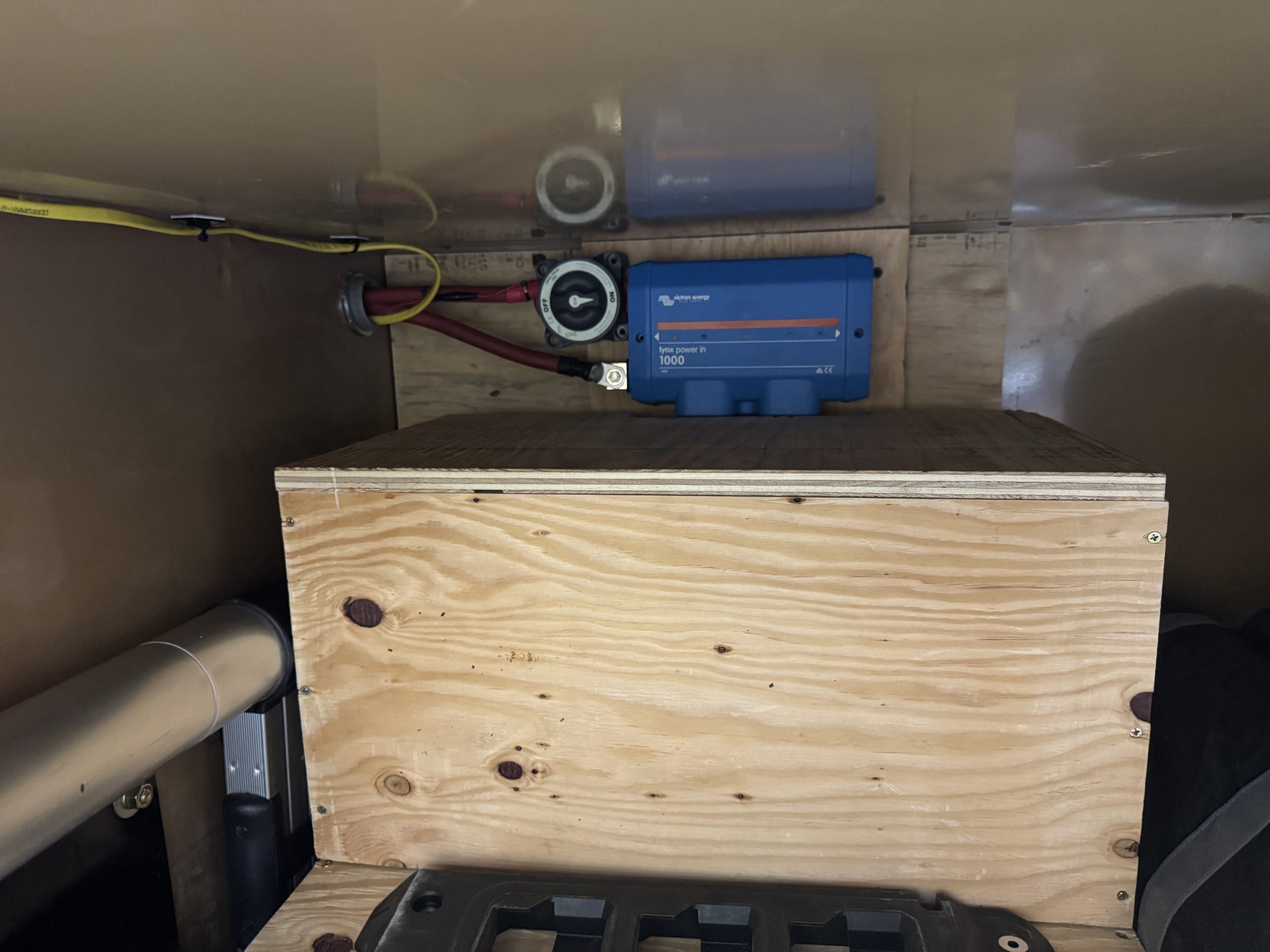
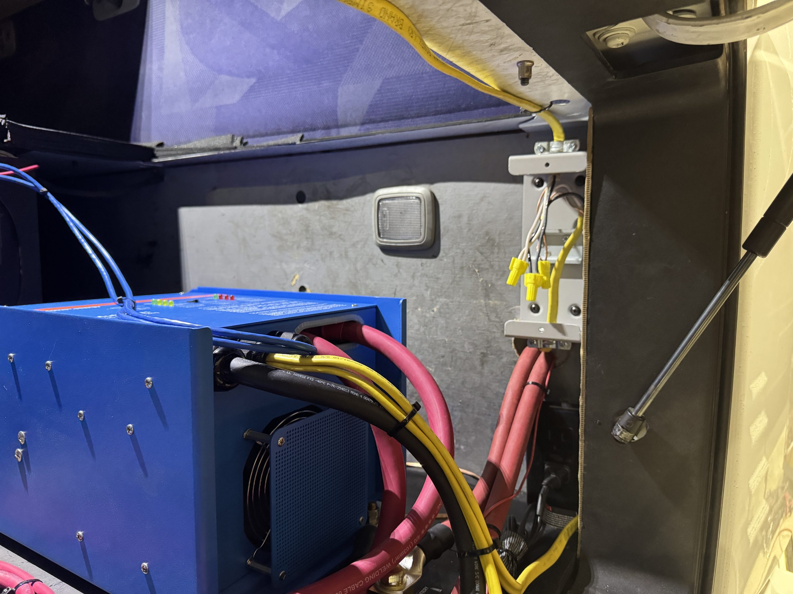
Once I had the majority of the equipment connections completed in the Jockey box, I began working on installing the battery bank in the drom box. After trying several battery layouts, I settled on having two of the batteries stand on end against the back wall of the drom box and the other two batteries sitting on the floor of the drom box in front of the vertical batteries. I built a custom battery box around the batteries to protect them and keep items stored in the drom box from coming in contact with any of the battery terminals. I made the battery box out of 3/4″ plywood and left it as bare wood because the floor of the drom box already had bare plywood on it. I connected the four batteries individually to a Lynx Power in with equal length 4/0 welding cables. (I ended up using all red sheathed welding cable because I had a bunch of it left over from other jobs. I used red heat shrink for all the lugs on the positive cables and black heat shrink for all the lugs on the negative cables to make it a little easier to determine positive from negative connections.) I added MRBF (Marine Rated Battery Fuse) holders with 300 amp MRBF fuses to each battery’s positive post. I mounted a Blue Blue Sea 3000 HD On/Off switch to the end of the positive bus bar coming out of the Lynx Power In. I then connected the Power In to the SmartShunt battery terminal and Lynx Distributor positive bus bar with 4/0 welding cable. I ran the cable out the side of the drom box and into the back wall of the Jockey box with two inch flexible conduit and water tight connectors. The flexible conduit will allow for the connection between the fixed drom box and the moving (air ride) cab/sleeper. I also used this conduit to run the main power wire for the shunt to a positive terminal in the Power in for more accurate battery voltage readings and to run a 12/2 Romex line into the sleeper from the Volvo AC distribution system to power an AC circuit in the drom box for plugs and lights. I installed an in line circuit breaker in this circuit in the Jockey box for added protection.
After I made all the connections, I powered up the system for programming and testing. Everything worked as expected. I added some Ruuvitag Bluetooth temperature sensors to the system and connected them to the Cerbo to monitor various temperatures (drom box, Jockey/Victron equipment box, sleeper, refrigerator and outdoor). I also added Mopeka Bluetooth tank sensors to the waste water and fresh water tanks in the custom hauler bed. I will be adding solr panels to the system as well. My plan is to mount the solar panels atop the drom box, even with the top of the sleeper cab. I plan to mount the panels one on top of the other and have the lower panel on slides so it can be deployed when the Volvo is parked and moved out of the way when it is traveling. I will update this page when I get a chance to complete the solar panel installation.